Andhra Pradesh BIEAP AP Inter 2nd Year Physics Study Material 11th Lesson Electromagnetic Waves Textbook Questions and Answers.
AP Inter 2nd Year Physics Study Material 11th Lesson Electromagnetic Waves
Very Short Answer Questions
Question 1.
What is the average wavelength of X-rays? (A.P. Mar. ’16 )
Answer:
The wavelength range of X-rays is from 10-8m(10nm) to 10-13 m (10-4 nm).
Average wavelength of X – rays = \(\frac{10+0.0001}{2}\) = 5.00005nm.
Question 2.
Give anyone use of infrared rays. (T.S. Mar. ’19)
Answer:
- Infrared radiation plays an important role in maintaining the Earth warm.
- Infrared lamps are used in physical therapy.
- Infrared detectors are used in Earth Satellites.
- These are used in taking photographs during conditions of fog, smoke, etc.
![]()
Question 3.
If the wavelength of electromagnetic radiation is doubled, what happens to the energy of photon ? (T.S. Mar. ’16)
Answer:
Photon energy (E) = hv = \(\frac{\mathrm{hc}}{\lambda}\)
E ∝ \(\frac{1}{\lambda}\)
Given λ1 = λ, λ2 = 2λ, E1 = E
\(\frac{\mathrm{E}_1}{\mathrm{E}_2}\) = \(\frac{\lambda_2}{\lambda_1}\)
\(\frac{E}{\mathrm{E}_2}\) = \(\frac{2 \lambda}{\lambda}\)
E2 = E/2
∴ The energy of photon reduces to half of its initial value.
Question 4.
What is the principle of production of electromagnetic waves ?
Answer:
If the charge is accelerated both the magnetic field and electric field will change with space and time, then electromagnetic waves are produced.
Question 5.
What is the ratio of speed of infrared rays and ultraviolet rays in vacuum ?
Answer:
The ratio of speed of infrared rays and ultraviolet rays in vacuum is 1 : 1.
All electromagnetic waves travel with same speed 3 × 10⁸ m /s in vacuum.
Question 6.
What is the relation between the amplitudes of the electric and magnetic fields in free space for an electromagnetic wave ?
Answer:
E0 = CB0
Where E0 = Amplitude of electric field.
B0 = Amplitude of magnetic field.
C = velocity of light.
![]()
Question 7.
What are the applications of microwaves ? (T.S. Mar. ’15)
Answer:
- Microwaves are used in Radars.
- Microwaves are used for cooking purposes.
- A radar using microwave can help in detecting the speed of automobile while in motion.
Question 8.
Microwaves are used in Radars, why ? (Mar. ’14)
Answer:
As microwaves are of smaller wavelengths, hence they can be transmitted as a beam signal in a particular direction. Microwaves do not bend around the comers of any obstacle coming in their path.
Question 9.
Give two uses of infrared rays. (A.P. Mar. ’19)
Answer:
- Infrared rays are used for producing dehydrated fruits.
- They are used in the secret writings on the ancient walls.
- They are used in green houses to keep the plants warm.
Question 10.
The charging current for a capacitor is 0.6 A. What is the displacement current across its plates?
Answer:
i = charging current for a capacitor = 0.6 A
i = id = \(\varepsilon_0 \frac{\mathrm{d} \phi_{\mathrm{B}}}{\mathrm{dt}}\)
∴ i = i = id = 0.6A
∴ Displacement current (id) = 0.6 A.
Short Answer Questions
Question 1.
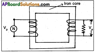
What does an electromagnetic wave consists of ? On what factors does its velocity in vacuum depend ?
Answer:
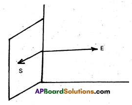
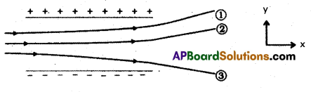
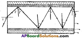
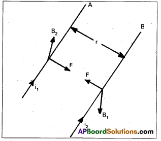
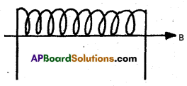
Maxwell concluded that the variation in electric and magnetic field vectors perpendicular to each other leads to the production of electromagnetic waves in space. They can travel in space even without any material medium. These waves are called electromagnetic waves.
According to Maxwell, electromagnetic waves are those waves in which there are sinusoidal variation of electric and magnetic field vectors at right angles to each other as well as at right angles to the direction of wave propagation. Thus electomagnetic waves have transverse nature.
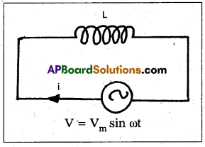
Electric field Ex = E0 Sin (kz – ωt)
Magnetic field By = B0 sin (kz – ωt)
Where K is propagation constant (K = \(\frac{2 \pi}{\lambda}\))
The velocity of electromagnetic waves C = \(\frac{1}{\sqrt{\mu_0 \varepsilon_0}}\)
Velocity of E.M waves depends on
- Permeability in free space (μ0).
- Permittivity in free space (ε0).
Velocity of e.m waves is 3 × 10⁸ m / s.
![]()
Question 2.
What is Greenhouse effect and its contribution towards the surface temperature of earth ?
Answer:
Green house effect: Temperature of the earth increases due to the radiation emitted by the earth is trapped by atmospheric gases like CO2, CH4, N2, Chlorofluoro carbons etc is called green house effect.
- Radiation from the sun enters the atmosphere and heat the objects on the earth. These heated objects emit infrared rays.
- These rays are reflected back to Earth’s surface and trapped in the Earth’s atmosphere. Due to this temperature of the earth increases.
- The layers of carbon dioxide (CO2) and low lying clouds prevent infrared rays to escape Earth’s atmosphere.
- Since day-by-day the amount of carbondioxide in the atmosphere increases, more infrared rays are entrapped in the atmosphere.
- Hence the temperature of the Earth’s surface increases day by day.
Long Answer Questions
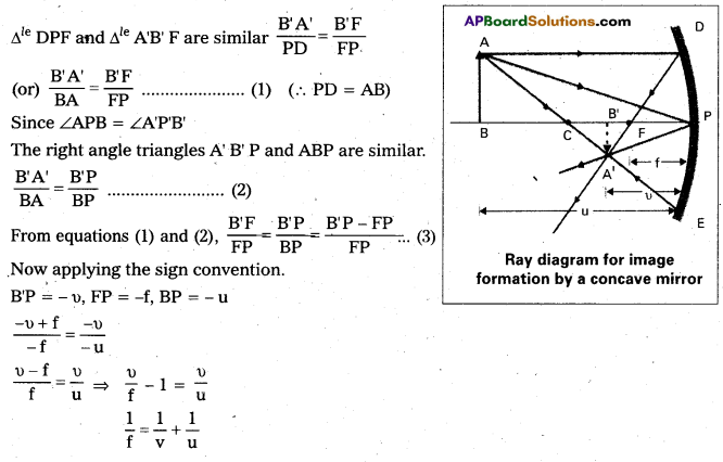
Question 1.
Give the brief history of discovery of knowledge of electromagnetic waves.
Answer:
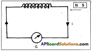
- Faraday from his experimental study of electromagnetic induction magnetic field changing with time, gives rise to an electric field.
- Maxwell in 1865 from his theoritical study concluded that, an electric field changing with time gives rise to magnetic field.
- It is a consequence of the displacement current being a source of magnetic field.
- It means a change in electric (or) magnetic field with time produces the other field.
- Maxwell concluded that the variation in electric and magnetic field vectors perpendicular to each other leads to the production of electromagnetic waves in space.
- These electromagnetic waves travel in space without any material medium.
- Both electric and magnetic fields vary with time and space and have the same frequency.
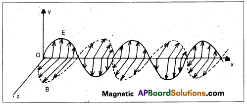
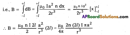
- The electric field vector \(\overrightarrow{\mathrm{E}}\) and magnetic field vector \(\overrightarrow{\mathrm{B}}\) are vibrating along y and z axis and propagation of electromagnetic waves along x – axis.
- Maxwell found that the electromagnetic waves travel in vacuum with a speed is given by
Where μ0 = 4π × 10-7 H/m = permeability in free space.
ε0 = 8.85 × 10⁻¹² c2 N-1 m-2 = permittivity in free space. - The velocity of electromagnetic waves in a medium is given by v = \(\frac{1}{\sqrt{\mu \varepsilon}}\)
- Maxwell also concluded that electromagnetic waves are transverse in nature.
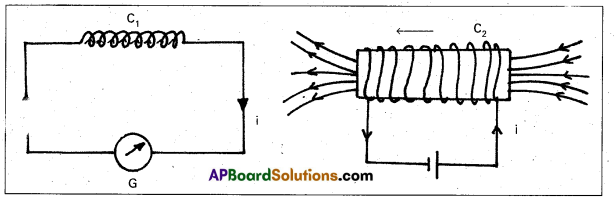
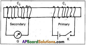
- In 1888 Hertz demonstrated experimentally the production and detection of E.M waves using spark oscillator.
- In 1895 Jagadish Chandra Bose was able to produce E.M waves of wavelength 5m.m to 25 m.m.
- 1899 Marconi was the first to establish a wireless communication at a distance of about 50 km.
![]()
Question 2.
State six characteristics of electromagnetic waves. What is Greenhouse effect ?
Answer:
Characteristics (or) properties of electromagnetic waves :
- Electromagnetic waves do not require any material medium for their propagation. They propagate in vacuum as well as in a medium.
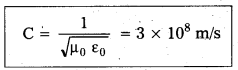
- Speed of E.M. waves in free space (or) vacuum is given by
C = \(\frac{1}{\sqrt{\mu_0 \varepsilon_0}}\) = 3 × 10⁸ m/s. - Speed of E.M waves in a medium is given by
v = \(\frac{1}{\sqrt{\mu \varepsilon}}\) - Electromagnetic waves are transverse in nature.
Electric field \(\overrightarrow{\mathrm{E}}\) and magnetic field \(\overrightarrow{\mathrm{B}}\) which constitute the E.M waves an mutually perpendicular to each other as well as perpendicular to the direction of propagation of the wave. - Electromagnetic waves are self sustaining electric and magnetic field oscillations in space.
- Electromagnetic waves transport energy.
Poynting vector (\(\overrightarrow{\mathrm{P}}\)) = \(\frac{1}{\mu_0}(\overrightarrow{\mathrm{E}} \times \overrightarrow{\mathrm{B}})\) - Relation between electric field vector E and magnetic field vector g in vacuum is given by
C = \(\frac{\mathrm{E}_0}{\mathrm{~B}_0}\) - Electromagnetic waves are not deflected by magnetic and electric fields.
- Electromagnetic waves can be reflected, refracted, interferenced, diffracted and polarised.
- Electromagnetic wave follow the superposition principle.
- Average electric energy density of E.M wave is given by
Uav = UE + UB
Uav = \(\frac{1}{2} \varepsilon_0 \mathrm{E}^2\) + \(\frac{1}{2} \cdot \frac{\mathrm{B}^2}{\mu_0}\)
Uav = 2UE = 2UB - Intensity of an E.M waves depends on its average energy density.
I = \(\frac{1}{2} \varepsilon_0 \mathrm{C} \mathrm{E}_0^2\) - E.M. waves carry momentum and exert radiation pressure is given by
P = \(\frac{\mathrm{F}}{\mathrm{A}}\) = \(\frac{1}{\mathrm{~A}} \frac{\mathrm{dp}}{\mathrm{dt}}\) = \(\frac{\text { Intensity (I) }}{C}\)
Green house effect:
The temperature of the Earth increases due to radiation emitted by the Earth.is trapped by atmospheric gases like CO2, CH4, N2O, chlorofluoro carbons etc is called green house effect.
Textual Exercises
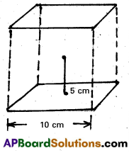
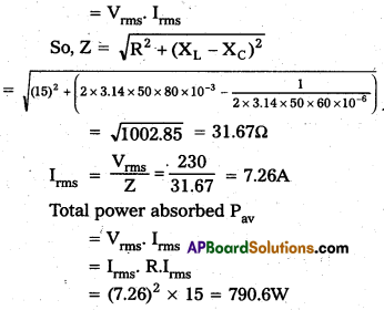
Question 1.
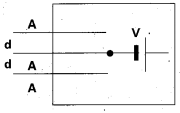
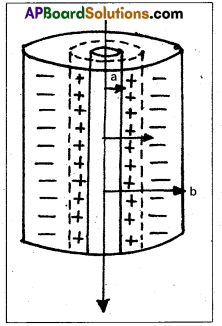
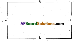
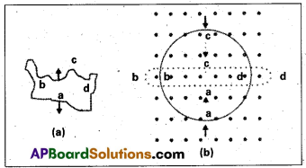
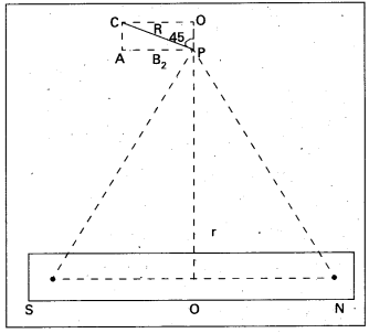
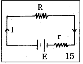
The figure shows a capacitor made of two circular plates each of radius 12cm, and separated by 5.0 cm. The capacitor is being charged by an external source (not shown in the figure). The charging current is constant and equal to 0.15A.
a) Calculate the capacitance and the rate of charge of potential difference between the plates.

b) Obtain the displacement current across the plates.
c) Is Kirchhoff’s first rule (junction rule) valid at each plate of the capacitor ? Explain.
Answer:
Given ε0 = 8.85 × 10⁻¹² C2 N-1 m-2
Here, R = 12cm = 0.12m, d = 5.0mm = 5 × 10⁻³m, I = 0.15A
Area, A = πR2 = 3.14 × (0.12)2m2
a) We know that capacity of a parallel plate capacitor is given by
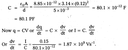
b) Displacement current is equal to conduction current i.e., 0.15 A.
c) Yes, Kirchhoffs first rule is valid at each plate of the capacitor provided. We take the current to be the sum of the conduction and displacement currents.
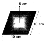
Question 2.
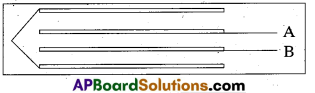
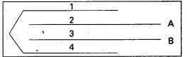
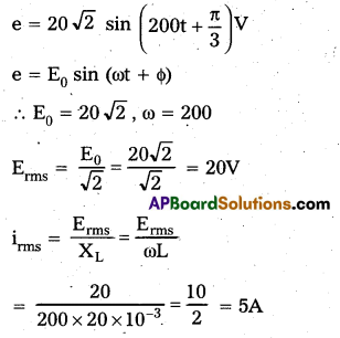
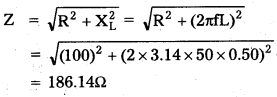
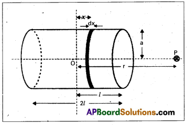
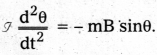
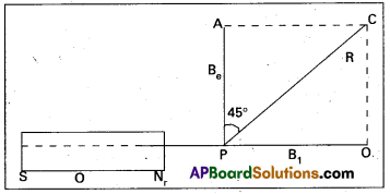
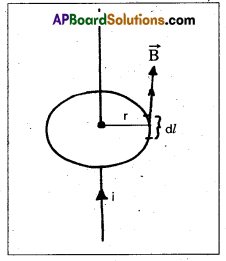
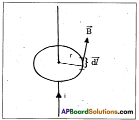
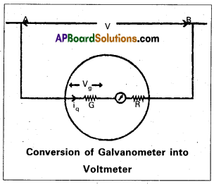
A parallel plate capacitor in the figure made of circular plates each of radius R = 6.0 cm has a capacitance C = 100 pF. The capacitor is connected to a 230 V ac supply with a (angular) frequency of 300 rad s-1.
a) What is the rms value of the conduction current ?
b) Is the conduction current equal to the displacement current ?
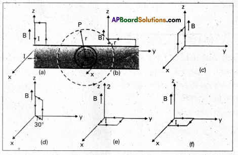
c) Determine the amplitude of B at a point 3.0 cm from the axis between the plates.

Answer:
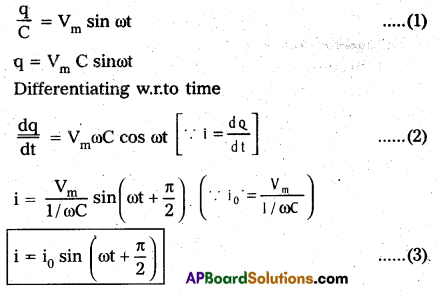
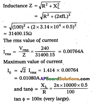
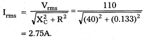
a) Irms = \(\frac{E_{\mathrm{fms}}}{X_c}\) = \(\frac{E_{\mathrm{rms}}}{\frac{1}{\omega C}}\) = Erms × ωC
∴ Irms = 230 × 300 × 100 × 10-12 = 6.9 × 10⁻⁶A = 6.9µA
b) Yes, I = Id where I is steady d.c or a.c. This is shown below
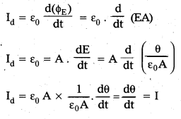
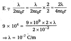
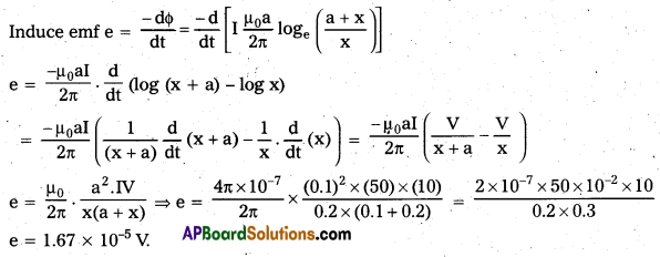
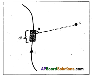
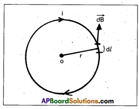
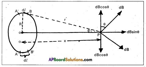
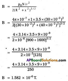
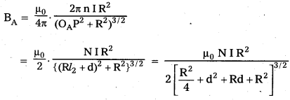
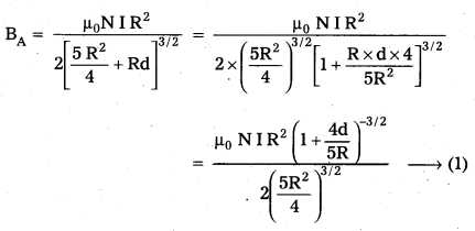
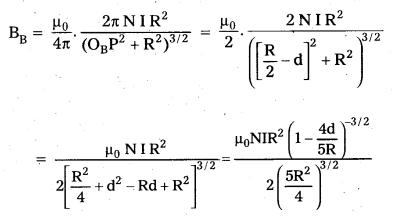
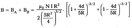
c) We know, B = \(\frac{\mu_0}{2 \pi} \times \frac{\pi}{R^2} \times I_d\)
The formula is valid even if Id is oscillating. As Id = I, therefore
B = \(\frac{\mu_0 r \mathrm{I}}{2 \pi \mathrm{R}^2}\)
If I = I0, the maximum value of current, then
Amplitude of B = max. value of B = \(\frac{\mu_0 \mathrm{rI}_0}{2 \pi \mathrm{R}^2}\) = \(\frac{\mu_0 \mathrm{r} \sqrt{2} \mathrm{I}_{\mathrm{rms}}}{2 \pi \mathrm{R}^2}\)
= \(\frac{4 \pi \times 10^{-7} \times 0.03 \times \sqrt{2} \times 6.9 \times 10^{-6}}{2 \times 3.14 \times(0.06)^2}\) = 1.63 × 10⁻¹¹T.
![]()
Question 3.
What physical quantity is the same for X-rays of wavelength 10-10m, red light of wavelength 6800 A and radiowaves of wavelength 500m?
Answer:
The speed in vacuum is same for all the given wavelengths, which is 3 × 10⁸ m/s.
Question 4.
A plane electromagnetic wave travels In vacuum aloñg z-direction. What can you say about the directions of its electric and magnetic field vectors ? If the frequency of the wave is 30 MHz, what is its wavelength?
Answer:
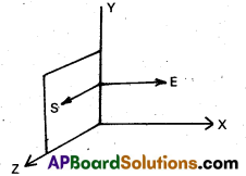
In electromagnetic wave, the electric field vector \(\overrightarrow{\mathrm{E}}\) and magnetic field vector \(\overrightarrow{\mathrm{B}}\) show their variations perpendicular to the direction of propagation of wave as well as perpendicular to each other. As the electromagnetic wave is travelling along z – direction, hence \(\overrightarrow{\mathrm{E}}\) and \(\overrightarrow{\mathrm{B}}\) show their variation in x – y plane.
wave length λ = \(\frac{\mathrm{c}}{\mathrm{v}}\) = \(\frac{3 \times 10^8 \mathrm{~m} / \mathrm{s}}{30 \times 10^6 \mathrm{~s}^{-1}}\) = 10m
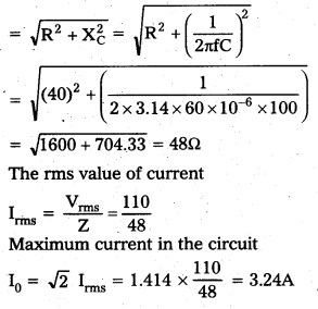
Question 5.
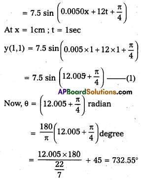
A radio can tune into any station in the 7.5 MHz to 12MHz band. What is-the corresponding wavelength band?
Answer:
λ1 = \(\frac{3 \times 10^8}{7.5 \times 10^6}\) = 40m
λ2 = \(\frac{3 \times 10^8}{12 \times 10^6}\) = 25m
Thus wavelength band is 40m to 25m.
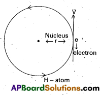
Question 6.
A charged particle oscillates about its mean equilibrium position with a frequency of 109 Hz. What is the frequency of the electromagnetic waves produced by the oscillator ?
Answer:
The frequency of electromagnetic wave is same as that of oscillating cliarged particle about its equilibrium position; which is 109Hz.
Question 7.
The amplitude of the magnetic field part of a harmonic electromagnetic wave in vacuum is B0 = 510 nT. What is the amplitude of the electric field part of the wave ?
Answer:
Here, B0 = 510nT = 510 × 10-9T
E0 = CB0 = 3 × 108 × 510 × 10-9 = 153 NC-1.
Question 8.
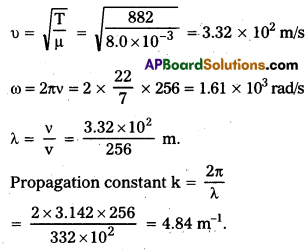
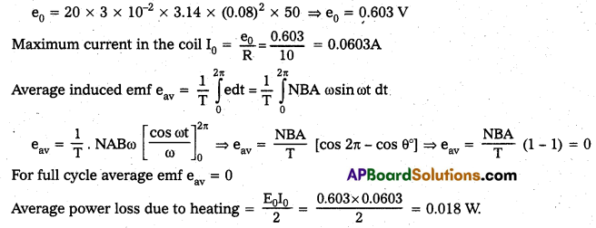
Suppose that the electric field amplitude of an electromagnetic wave is E0 = 120 N/C and that its frequency is v = 50.0 MHz.
(a) Determine. B0, ω, k, and λ.
(b) Find expressions for E and B.
Answer:
a)
B0 = \(\frac{E_0}{\mathrm{c}}\) = \(\frac{120}{3 \times 10^8}\) = 4 × 10⁻⁷ T
ω = 2πv = 2 × 3.14 × (50 × 106) = 3.14 × 10⁸ rad/s
K = \(\frac{\omega}{\mathrm{C}}\) = \(\frac{3.14 \times 10^8}{3 \times 10^8}\) = 1.05 rad/m
λ = \(\frac{C}{V}\) = \(\frac{3 \times 10^8}{50 \times 10^6}\) = 6.00 m
b) Expression for \(\overrightarrow{\mathrm{E}}\) is E = E0 sin (kx – ωt)
= (120 N/c) Sin [(1.05 rad/m) x – (3.14 × 10⁸ rad /s)t] \(\hat{\mathrm{j}}\)
Expression for \(\overrightarrow{\mathrm{B}}\) is B = B0 sin (kx – ωt)
= (4 × 10⁻⁷ T) sin [(1.05 rad/m) x – (3.14 × 10⁸ rad/s)t] \(\hat{\mathrm{k}}\).
![]()
Question 9.
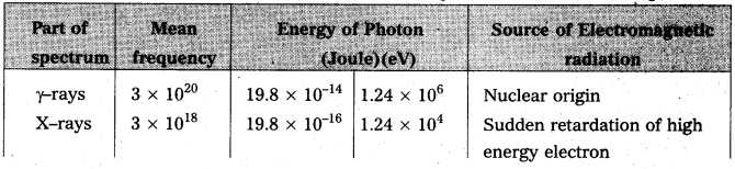
The terminology of different parts of the electromagnetic spectrum is given in the text. Use the formula E = hv (for energy of a quantum of radiation: photon) and obtain the photon energy in units of eV for different parts of the electromagnetic spectrum, in what way are the different scales of photon energies that you obtain related to the sources of electromagnetic radiation ?
Answer:
Energy of a photon of frequency v is given by E = hv joules = \(\frac{\mathrm{hv}}{1.6 \times 10^{-19} \mathrm{ev}}\)
Where h = 6.6 × 10⁻³⁴ J. The energy of photon of different parts of electromagnetic spectrum in joules and eV are shown in table below, along with their sources of origin.
Question 10.
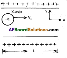
In a plane electromagnetic wave, the electric field oscillates sinusoidally at a frequency of 2.0 × 10¹⁰ Hz and amplitude 48 V m-1.
a) What is the wavelength of the wave ?
b) What is the amplitude of the oscillating magnetic field ?
c) Show that the average energy density of the E field equals the average energy density of the B field. [C = 3 × 10⁸ ms-1].
Answer:
Here, v = 2.0 × 10¹⁰Hz, E0 = 48 Vm-1, C = 3 × 10⁸ m/s
a) wavelength of the wave, λ = \(\frac{C}{v}\) = \(\frac{3 \times 10^8}{2.0 \times 10^{10}}\) = 1.5 × 10⁻² m
b) Amplitude of oscillating magnetic field,
B0 = \(\frac{E_0}{C}\) = \(\frac{48}{3 \times 10^8}\) = 1.6 × 10⁻⁷T
c) For average energy density
UE = \(\frac{1}{2} \varepsilon_0 \mathrm{E}_0^2\) …… (1)
We know that \(\frac{E_0}{B_0}\) = C
Putting in Eq (1)
UE = \(\frac{1}{4} \varepsilon_0 \cdot C^2 \mathrm{~B}_0^2\) …. (2)
Speed of Electro magnetic waves, C = \(\frac{1}{\sqrt{\mu_0 \mathrm{E}_0}}\)
Putting in Eq (2) We get.
UE = \(\frac{1}{4} \varepsilon_0 B_0^2 \cdot \frac{1}{\mu_0 \varepsilon_0}\)
UE = \(\frac{1}{4} \cdot \frac{\mathrm{B}_{\mathrm{O}}^2}{\mu_0}=\frac{\mathrm{Bo}^2}{2 \mu_0}\) = μB
Thus, the average energy density of E field equals the average energy density of B field.
Additional Exercises
Question 1.
Suppose that the electric field part of an electromagnetic wave in vacuum is E = {(3.1 N/C) cos [(1.8 rad/m) y + {5.4 × 10⁶ rad /s} t]} i.
a) What is the direction of propagation ?
b) What is the wavelength λ ?
c) What is the frequency v ?
d) What is the amplitude of the magnetic field part of the wave ?
e) Write an expression for the magnetic field part of the wave.
Answer:
a) From the given question it is clear that direction of motion of e.m. wave is along negative y direction i.e along – \(\hat{\mathrm{j}}\)
b) Comparing the given question with equation E = E0 cos (ky + ωt).
We have, K = 1.8 rad/m, ω = 5.4 × 10⁸ rad/s, E0 = 3.1 N/C
λ = \(\frac{2 \pi}{\mathrm{k}}\) = \(\frac{2 \times(22 / 7)}{1.8}\) = 3.492 m ≈ 3.5m
c) V = \(\frac{\omega}{2 \pi}\) = \(\frac{5.4 \times 10^8}{2 \times\left(\frac{22}{7}\right)}\) = 85.9 × 10⁶ ≈ 86MHz
d) B0 = \(\frac{\mathrm{E}_0}{\mathrm{C}}\) = \(\frac{3.1}{3 \times 10^8}\) = 1.03 × 10⁻⁸T ≈ 10.3nT
e) B = B0 cos (ky + ωt) \(\hat{\mathbf{k}}\) = (10.3nT) cos [(1.8 rad/m/y + (5.4 × 10⁸ rad / s)t] \(\hat{\mathbf{k}}\)
Question 2.
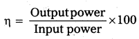
About 5% of the power of a 100 W light bulb is converted to visible radiation. What is the average intensity of visible radiation
a) at a distance of lm from the bulb ?
b) at a distance of 10 m ?
Assume that the radiation is emitted isotropically and neglect reflection.
Answer:
a) Intensity,
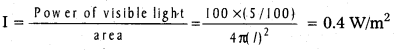
b) I = \(\frac{100 \times(5 / 100)}{4 \pi(10)^2}\) = 4 × 10⁻³ W/m2
Question 3.
Use the formula λm T = 0.29 cm K to obtain the characteristic temperature ranges for different parts of the electromagnetic spectrum. What do the numbers that you obtain tell you ?
Answer:
We know, every body at given temperature T1 emits radiations of all wavelengths in certain range. For a black body, the wavelength corresponding to maximum intensity of radiation at a given temperature.
λm T = 0.29cmk or T = \(\frac{0.29}{\lambda_{\mathrm{m}}}\)
For λm = 10-6m = 10-4cm, T = \(\frac{0.29}{10^{-4}}\) = 2900 k.
Temperature for other wavelengths can be similarly found. These numbers tell us the temperature ranges required for obtaining radiations in different parts of e.m spectrum. Thus to obtain visible radiation, say, λm = 5 × 10⁻⁵cm, the source should have a temperature
T = \(\frac{0.29}{5 \times 10^{-5}}\) = 6000 k
It is to be noted that, a body at lower temperature will also produce this wavelength but not with maximum intensity.
Question 4.
Given below are some famous numbers associated with electromagnetic radiations in different contexts in physics. State the part of the electromagnetic spectrum to which each belongs.
a) 21 cm (wavelength emitted by atomic hydrogen in interstellar space).
b) 1057 MHz (frequency of radiation arising from two close energy levels in hydrogen; known as Lamb shift).
c) 2.7 K [temperature associated with the isotropic radiation filling all space-thought to be a relic of the ‘big-bang’ origin of the universe].
d) 5890 A – 5896 A [double lines of sodium]
e) 14.4 keV [energy of a particular transition in 57Fe nucleus associated with a famous high resolution spectroscopic method (Mossbauer spectroscopy).
Answer:
a) This wavelength corresponds to radiowaves.
b) This frequency also corresponds to radiowaves.
c) Given T = 2.7 K As λm T = 0.29cm °k
∴ λm = \(\frac{0.29}{\mathrm{~T}}\) = \(\frac{0.29}{2.7}\) ≈ 0.11cm
This wavelength corresponds to microwave region of the electromagnetic spectrum.
d) This wavelength lies in the visible region of the electromagnetic spectrum.
e) Here, Energy E = 14.4KeV = 14.4 × 103 × 1.6 × 10-19J
As E = hv
∴ v = \(\frac{E}{h}\) = \(\frac{14.4 \times 10^3 \times 1.6 \times 10^{-19}}{6.6 \times 10^{-34}}\) ≈ 3 × 10¹¹ MHz
This frequency lies in the X-ray region of electromagnetic spectrum.
![]()
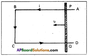
Question 5.
Answer the following questions :
a) Long distance radio broadcasts use short-wave bands. Why ?
b) It is neccessary to use satellites for long distance TV transmission. Why ?
c) Optical and radio telescopes are built on the ground, but X-ray astronomy is possible only from satellites orbiting the earth. Why ?
d) The small ozone layer on top of the stratosphere is crucial for human survival. Why ?
e) If the earth did not have an atmosphere, would its average surface temperature be higher or lower than what it is now ?
f) Some scientists have predicted that a global nuclear war on the earth would be followed by a severe ‘nuclear winter’ with a devastating effect on life on earth. What might be the basis of this prediction ?
Answer:
a) It is so because ionosphere reflects the waves in these bands.
b) Yes, television signals being of high frequency are not reflected by ionosphere, Therefore to reflect them satellites are needed. That is why, satellites are used for long distance TV transmission.
c) Optical and radiowaves can penetrate the atmosphere where as X-rays being of much smaller wavelength are absorbed by the atmosphere. That is why we can work with optical and radio telescopes on earth’s surface but X-ray astronomical telescopes must be used on the satellite orbiting above the earth’s atmosphere.
d) The small ozone layer present on the top of the stratosphere absorbs most of ultraviolet radiations from the sun which are dangerous and cause genetic damage to living cells, prevents them from reaching the earth’s surface and thus helps in the survival of life.
e) The temperature of earth would be lower because the green house effect of atmosphere would be absent.
f) The clouds by a global nuclear war would perhaps cover most parts of sky preventing solar light from reaching many parts of globe. This would cause a winter.


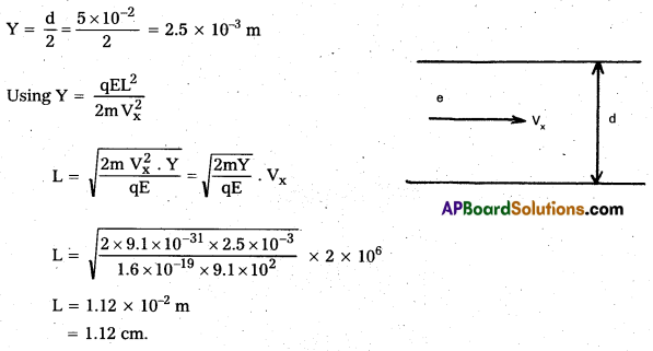
 Farads (In air)