Andhra Pradesh BIEAP AP Inter 2nd Year Physics Study Material 9th Lesson Electromagnetic Induction Textbook Questions and Answers.
AP Inter 2nd Year Physics Study Material 9th Lesson Electromagnetic Induction
Very Short Answer Questions
Question 1.
What did the experiments of Faraday and Henry show?
Answer:
The discovery and understanding of electromagnetic induction are based on a long series of experiments carried out by Faraday and Henry.
Question 2.
Define magnetic flux.
Answer:
Magnetic flux is defined as the number of magnetic lines of force crossing through the surface.
ϕB = \(\overrightarrow{\mathrm{B}} \cdot \overrightarrow{\mathrm{A}}\) = BA cos θ
C.G.S unit → Maxwell
S.I. unit → Weber (wb)
Magnetic flux is a scalar.
![]()
Question 3.
State Faraday’s law of electromagnetic induction.
Answer:
“Magnitude of induced e.m.f is directly proportional to the rate of change of magnetic flux”
ε ∝ \(-\frac{d \phi}{d t}\)
Question 4.
State Lenz’s law.
Answer:
The direction of induced e.m.f (or) current is such that it opposes the cause which produce it. Lenz’s law is in accordance with law of conservation of energy.
Question 5.
What happens to the mechanical energy (of motion) .when a conductor is moved in a uniform magnetic field ?
Answer:
Motional e.m.f is produced to the motion of the conductor,in a magnetic field.
Motion e.m.f (ε) = Blυ
Question 6.
What are Eddy currents ? (T.S. Mar. ’19; A.P. Mar. ’15)
Answer:
Eddy currents (or) Foucault currents : The induced circulating currents produced in a conductor itself due to change in magnetic flux linked with the conductor are called Eddy currents.
Due to Eddy currents, the energy is dissipated in the form of heat energy.
Question 7.
Define ‘inductance’.
Answer:
Inductance is a coefficient of electromagnetic induction and is an intrinsic property of a material just like capacitance.
Inductance is an important scalar quantity which depends upon the geometry (i.e, dimensions) of a coil.
![]()
Question 8.
What do you understand by ‘self inductance’ ?
Answer:
Self inductance of a coil is defined as the induced e.m.f produced in the coil through which the rate of change of current is unity.
ε = \(-\mathrm{L} \frac{\mathrm{dI}}{\mathrm{dt}}\) ; ε = -L, If \(\frac{\mathrm{dI}}{\mathrm{dt}}\) = 1 A/s.
Short Answer Questions
Question 1.
Obtain an expression for the emf induced across a conductor which is moved in a uniform magnetic field which is perpendicular to the plane of motion.
Answer:
Consider a conductor PQ of length l moving freely in a uniform magnetic field \(\overrightarrow{\mathrm{B}}\) with uniform velocity u on a rectangular conductor ABCD. Let any arbitrary charge q in the conductor also move in the field with same velocity.
Magnitude of Lorentz force on this charge (F) = Bqυ —– (1)
Workdone in moving the charge from P to Q is given by
W = Force × displacement
W = Bqυ × l —– (2) (∵ Direction of force on the charge as per Fleming’s left hand rule)
Electromotive force (ε) = \(\frac{W}{Q}\)
ε = \(\frac{\mathrm{Bqv} l}{\mathrm{q}}\) ⇒ ε = Blυ —- (3)
Question 2.
Describe the ways in which Eddy currents are used to advantage. (A.P. Mar. ’16, AP & T.S. Mar. ’15)
Answer:
Eddy currents are used to advantage in
- Magnetic braking in trains : A strong magnetic field is applied across the metallic drum rotating with the axle of the electric train. Thus large eddy currents are produced in the metallic drum. These currents oppose the motion of the drum and hence the axle of the train which ultimately makes the train come to rest.
- Induction Motor: Eddy currents are used to rotate the short circuited rotor of an induction motor. Ceiling fans are also induction motors which run on single phase alternating current.
- Electromagnetic damping : Certain galvanometers have a fixed core made of non magnetic metallic material. When the coil oscillates, the eddy currents generated in the core oppose the motion and bring the coil to rest quickly.
- Induction furnace : Induction furnace can be used to produce high temperatures and can be utilised to prepare alloys, by melting the constituent metals. A high frequency alternating current is passed through a coil. The eddy currents generated in the metals produce high temperatures sufficient to melt it.
- Analogue energy meters : Concept of eddy currents is used in energy meters to record
the consumption of electricity. Aluminium disc used in these meters get induced due to varying magnetic field. It rotates due to eddy currents produced in it.
Question 3.
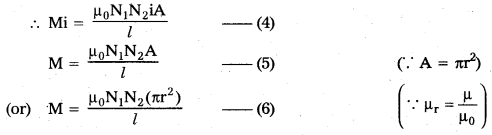
Obtain an expression for the mutual inductance of two long co-axial solenoids. (A.P. Mar. ’19)
Answer:
Consider two solenoids as shown in figure. The length of primary coil be l and are a of cross section A. Let N1 and N2 are the total number of turns in the primary and secondary solenoids. Let n1 and n2 be the number of turns per unit length
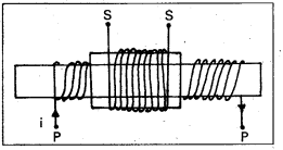
(n1 = \(\frac{\mathrm{N}_1}{l}\) and n2 = \(\frac{\mathrm{N}_2}{l}\)). Current in the primary coil is i.
∴ Magnetic field inside the primary (B) = μ0n1 I = μ0\(\frac{\mathrm{N}_1}{l}\) I —– (1)
Magnetic flux through each turn of primary
ϕB = \(\overrightarrow{\mathrm{B}} \cdot \overrightarrow{\mathrm{A}}\) = μ0\(\frac{\mathrm{N}_1}{l} \mathrm{I} \times \mathrm{A}\) —— (2)
The same magnetic flux is linked with the secondary coil.
∴ Total magnetic flux linked with secondary = μ0\(\frac{\mathrm{N}_1 \mathrm{i}}{l} \times \mathrm{A} \times \mathrm{N}_2\) ——– (3)
If M be mutual inductance of the two coils, the total flux linked with the secondary is Mi
Question 4.
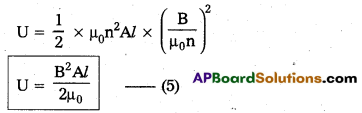
Obtain an expression for the magnetic energy stored a solenoid in terms of the magnetic field, area and length of the solenoid.
Answer:
When the current flows through the inductor of inductance L, an e.m.f is induced in it is given by
ε = -L\(\frac{\mathrm{dI}}{\mathrm{dt}}\) —– (1)
(-ve sign shows that e.m.f opposes the passage of current)
Let an infinite small charge dq be driven through the inductor. So the work done by the external voltage is given by
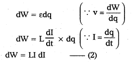
Total work done to maintain the maximum current (I0) is given by
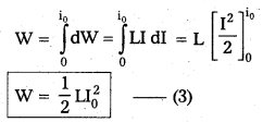
This work done is stored in the form of potential energy in the magnetic field (U)
In case of solenoid B = μ0nI0 (or) I0 = \(\frac{\mathrm{B}}{\mu_0 \mathrm{n}}\) and L = μ0n2Al
Long Answer Questions
Question 1.
Outline the path-breaking experiments of Faraday and Henry and highlight the contributions of these experiments to our understanding of electromagnetism.
Answer:
Faraday’s and Henry’s experiments :
Experiment 1: A magnet induces current due to relative motion
- The apparatus consists of a coil with a galvanometer G and a bar magnet.
- When the bar magnet (NS) was at rest, the galvanometer shows no deflection.
- When North pole of the bar magnet moved towards the coil, galvanometer shows the deflection in one direction indicating the flow of current in the coil.
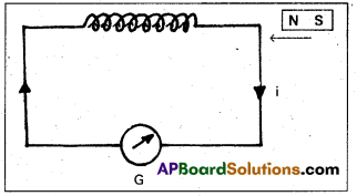
- When North pole of the bar magnet moved away from the coil, galvanometer again showed the deflection but now in the opposite direction.
- The deflection of the galvanometer was large when the bar magnet was moved faster towards (or) away from the coil.
- When south pole of the magnet was brought near the coil (or) moved away from the coil, the deflections in the galvanometer are opposite to that observed with the north pole for similar movements.
Conclusion:
- Whenever there is a relative motion between a coil and a magnet, induced current flows through the coil.
- Large induced e.m.f. (or) current is produced in the coil if the relative motion between magnet and the coil is large.
Experiment 2 : Current induces current due to relative motion of coils :
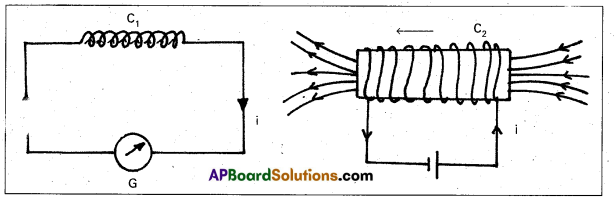
- The bar magnet is replaced by a secondary coil C2 connected to a battery as shown in figure.
- The steady current in the coil C2 produces a steady magnetic field.
- As coil C2 is moved towards the coil C1, the galvanometer shows a deflection. This indicates current is induced in the coil C1.
- When coil C2 is moved away, the galvanometer shows a deflection again, but opposite direction.
- The deflection lasts as long as coil C2 is in motion.
- When the coil C2 is held fixed and C1 is moved, the same effects are observed.
Conclusion : Induced e.m.f (or) current is produced, when there is a relative motion between the coils.
Experiment 3: Changing current, Induces current without relative motion:
- Faraday showed that this relative motion is not an absolute requirement.
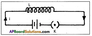
- Figure shows two coils C1 and C2 held stationary.
- Coil C1 is connected to a battery through a tap key K and coil C2 is connected to a galvanometer (G).
- it is observed that the galvanometer shows a momentary deflection when the tap key K is pressed.
- The pointer in the galvanometer returns to zero immediately.
- If the key is held pressed continuously, there is no deflection in the galvanometer.
- When the key is released, the galvanometer shows deflection again but in the opposite direction.
- Deflection of the galvanometer increases a lot when wooden bar is replaced by iron bar.
![]()
Question 2.
Describe the working of a AC generator with the aid of a simple diagram and necessary expressions.
Answer:
“An electrical machine used to convert mechanical energy into electrical energy is known as A.C generator/altemator”.
Principle : It works on the principle of electromagnetic induction.
Construction :
- Armature : Armature coil (ABCD) consists of a large number of turns of insulated copper wire wound over a soft iron core.
- Strong field magnet : A strong permanent magnet (or) an electromagnet whose poles (N and S) are cylindrical in shape used as a field magnet. The armature coil rotates between the pole pieces of the field magnet.
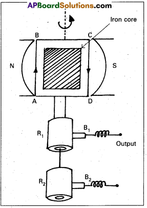
- Slip rings: The two ends of the armature coil are connected to two brass slip rings R1 and R2. These rings rotate along with the armature coil.
- Brushes : Two carbon brushes B1 and B2 are pressed against the slip rings. The brushes remain fixed while slip rings rotate along with the armature. These brushes are connected to the load through which the out put is obtained.
Working : When the armature coil ABCD rotates is the magnetic field provided by the strong field magnet, it cuts the magnetic line of force. The magnetic flux linked with the coil changes due to the rotation of the armature and hence induced e.m.f is set up in the coil.
The current flows out through the brush B in one direction of half of revolution and through the brush B2 in the next half revolution in the reverse direction. This process is repeated, therefore e.m.f produced is of alternating nature.
Theory:
- When the coil is rotated with a constant angular velocity (ω)
- The angle between the normal to the coil and magnetic field \(\overrightarrow{\mathrm{B}}\) at any instant is given by θ = ωt —— (1)
- The component of magnetic field normal to the plane of the coil = B cos θ = B cosωt —— (2)
- Magnetic flux linked with the single turn of the coil = (B cos ωt) A —— (3)
where A is the area of the coil, if the coil has n turns - Total magnetic flux linked with the coil (ϕ) = n(B cos ωt) A —– (4)
According to Faraday’s law,
ε = \(-\frac{\mathrm{d} \phi}{\mathrm{dt}}\) = \(-\frac{\mathrm{d}}{\mathrm{dt}}\)(nBA cos ωt) = -nBA(-ω sin ωt)
ε = nBA ω sin ωt —— (5)
Where nBAω is the maximum value of e.m.f. (ε0)
ε = ε0 sin ωt —– (6) (∵ ω = 2πυ)
Instantaneous current is the circuit is given by
I = \(\frac{\varepsilon}{\mathrm{R}}\) = \(\frac{\varepsilon_0}{\mathrm{R}}\) sin ωt [∵ i = \(\frac{\varepsilon_0}{\mathrm{R}}\)]
I = I0 sin ωt
The direction of the current changes periodically and therefore the current is called alternating current (a.c.).
Textual Exercises
Question 1.
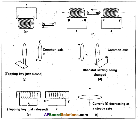
Predict the direction of induced current in the situations described by the following (a) to (f).
Answer:
a) Here south pole is moving towards the coil, so according to Lenz’s law this end becomes s-pole. (To oppose the motion of south pole by repelling it). Hence, the direction of current is clockwise (by using clock rule) and the current flows from p to q.
b) In coil p-q at the end q ⇒ s-pole is moving towards end q, so it behaves like a south pole (by lenz’s law). The direction of current is clockwise (by clock rule) i.e. from p to q. North pole is moving away so this end will behave like south pole (To oppose its away motion by attracting it). In coil x-y, S-pole is induced (by Lenz’s law) and the direction of current is clockwise i.e. x to y.
c) As the tapping key is just, closed, the current in coil increases so, the magnetic flux and field increases. According to Maxwell’s right hand grip rule, the direction of magnetic field is left wards. Thus, the direction of induced current in the neighbouring coil is such that it try to decrease the field, thus the direction of field in the neighbouring coil should be rightwards i.e., according to Maxwell’s right hand rule the direction of induced current is anti clock wise i.e. xyz.
d) As the rheostat setting is changed, the current is changed. The direction of field due to the coil is leftwards according to Maxwell’s right hand grip rule. The direction of induced current in the left coil is such that the magnetic field produced by it in rightwards, thus the direction of current in left coil is Anticlockwise i.e from zyx.
e) As the key is just released, the current which is flowing anticlockwise goes on decreasing. Thus, the induced current developed in such a sense the magnetic field due to left coil increases (which is towards right). So, the magnetic field due to the right coil should also towards right and hence the induced current is in anticlockwise, i.e., x to yx – direction.
f) The magnetic field lines due to the current carrying wire are in the plane of the loop. Hence, no induced current is produced in the loop (because no flux lines crosses the area of loop).
Question 2.
Use Lenz’s law to determine the direction of induced current in the situations described by fig. a, b.
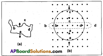
(a) A wire of irregular shape turning into a circular shape.
(b) A circular loop being deformed into a narrow straight wire.
Answer:
a) Here, the direction of magnetic field is perpendicularly inwards to the plane of paper. If a wire of irregular shape turns into a circular shape then its area increases (∵ the circular loop has greater area than the loop of irregular shape) so that the magnetic flux linked also increases. Now, the induced current is produced in a direction such that it decreases the magnetic field (i.e.) the current will flow in such a direction so that the wire forming the loop is pulled inwards in all directions (to decreases the area) i.e., current is in anticlockwise direction, i.e., adcba
b) When a circular loop deforms into a narrow straight wire, the magnetic flux linked with it also decreases. The current induced due to change in flux will flow in such a direction that it will oppose the decrease in magnetic flux so it will flow anti clockwise i.e along a’d’c’b’a’, due to which the magnetic field produced will be out of the plane of paper.
![]()
Question 3.
A long solenoid with 15 turns per cm has a small loop of area 2.0 cm2 placed inside the solenoid normal to its axis. If the current carried by the solenoid changes steadily from 2.0 A to 4.0 A in 0.1 s, what is the induced emf in the loop while the current is changing ?
Solution:
Given number of turns (n) = 15 per cm = 1500 per metre. .
Area of small loop A = 2 cm2 = 2 × 10⁻⁴m2
Change in current \(\frac{\mathrm{dI}}{\mathrm{dt}}\) = \(\frac{4-2}{0.1}\) = \(\frac{2}{0.1}\) = 20 A/s
Let e be the induced emf, According to Faraday’s law,
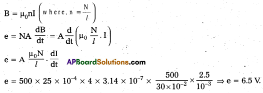
e = \(\frac{\mathrm{d} \phi}{\mathrm{dt}}\) = \(\frac{\mathrm{d}}{\mathrm{dt}}\)(BA) or e = \(\text { A. } \frac{\mathrm{dB}}{\mathrm{dt}}\) (∵ ϕ = BA)
e = A. \(\frac{\mathrm{d}}{\mathrm{dt}}\left(\mu_0 \mathrm{nI}\right)\) (∵ Magnetic field inside the solenoid B = μ0nI)
or e = Aμ0n\(\frac{\mathrm{dI}}{\mathrm{dt}}\)
e = 2 × 10-4 × 4 × 3.14 × 10-7 × 1500 × 20
e = 7.5 × 10⁶v (∵ μ0 = 4π × 10-7) Thus, the induced emf in the loop is 7.5 × 10⁶V.
Question 4.
A rectangular wire loop of sides 8 cm and 2 cm with a small cut is moving out of region of uniform magnetic field of magnitude 0.3 T directed normal to the loop. What is the emf developed across the cut if the velocity of the loop is 1 cm s-1 in a direction normal to the (a) longer side, (b) shorter side of the loop ? For how long does the induced voltage last in each case ?
Solution:
Given length of the loop l = 8 cm = 8 × 10⁻² m.
Width of the loop b = 2 cm = 2 × 10⁻² m.
Velocity of the loop = 1 cm/s = 0.01 m/s.
Magnitude of magnetic field (B) = 0.3
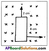
a) When velocity is normal to the longer side .
(l = 8 cm = 8 × 10⁻² m)
In this case, motional emf
e = B/υ = 0.3 × 8 × 10-2 × 0.01 = 2.4 × 10⁻⁴ V
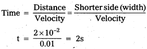
b) When velocity is normal to the shorter side
(l = 2cm = 2 × 10⁻² m)
In this case, the developed emf
e = Blυ = 0.3 × 2 × 10-2 × 0.01
e = 0.6 × 10⁻⁴ V.
Question 5.
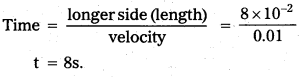
A 1.0 m long metallic rod is rotated with an angular frequency of 400 rad s-1 about an axis normal to the rod passing through its one end. The other end of the rod is in contact with a circular metallic ring. A constant and uniform magnetic field of 0.5 T parallel to the axis exists everywhere. Calculate the emf developed between the centre and the ring.
Solution:
Length of rod l = 1 m
Angular frequency of rod ω = 400 rad/s
Magnetic field B = 0.5 T
The linear velocity of fixed end = 0
The linear velocity of other end = lω (∵ V = rω)
Average linear velocity V = \(\frac{0+l \omega}{2}\)
V = \(\frac{l \omega}{2}\) —– (i) By using the formula of motional emf,
e = Bυl = \(\frac{\mathrm{B} l \omega}{2}\) (from equation (i)), e = \(\frac{0.5 \times 1 \times 400 \times 1}{2}\), e = 100.
Thus, the emf developed between the centre and ring is 100 V
![]()
Question 6.
A circular coil of radius 8.0 cm and 20 turns is rotated about its vertical diameter with an angular speed of 50 rad s-1 in a uniform horizontal magnetic field of magnitude 3.0 × 10⁻² T. Obtain the maximum and average emf induced in the coil. If the coil forms a closed loop of resistance 10Ω, calculate the maximum value of current in the coil. Calculate the average power loss due to Joule heating. Where does this power come from ?
Solution:
Given radius of coil = 8 cm = 0.08 m, Number of turns = 20
Resistance of closed loop = 10Ω, Angular speed ω = 50 rad/s
Magnitude of magnetic field B = 3 × 10⁻² T
Induced emf produced in the coil e = NBA W sin ωt
For maximum emf, sin ωt = 1
∴ Maximum emf e0 = NBAω
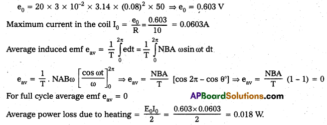
The source of power dissipated as heat in the coil is the external rotar. The current induced in the coil causes a torque which opposes the rotation of the coil, so the external agent rotar counter this torque to keep the coil rotating uniformly.
Question 7.
A horizontal straight wire 10 m long extending from east to west is falling with a speed of 5.0 m s-1, at right angles to the horizontal component of the earth’s magnetic field, 0.30 × 10⁻⁴ Wb m2.
(a) What is the instantaneous value of the emf induced in the wire ?
(b) What is the direction of the emf ?
(c) Which end of the wire is at the higher electrical potential ?
Solution:
Given, velocity of straight wire = 5 m/s
Magnetic field of straight wire,
B = 0.30 × 10⁻⁴ Wb/m2
length of wire l = 10m
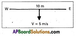
a) Emf induced in the wire e = B/υsin θ
Here, θ = 90°
∴ sin θ = 1 .
(∴ wire is falling at right angle to earth’s horizontal magnetic field component)
= 0.3 × 10-4 × 10 × 5 = 1.5 × 10⁻³ V.
b) According to the Fleming’s right hand rule, the force is downward, then the direction of induced emf will be from west to east.
c) As the direction of induced emf or current is from west to east, the west end of the wire is at higher potential.
(∵ current always flows from a point at higher potential to a point at lower potential).
Question 8.
Current in a circuit falls from 5.0 A to 0.0 A in 0.1 s. If an average emf of 200 V induced, give an estimate of the self-inductance of the circuit. (T.S. Mar. ’16, Mar. ’14)
Solution:
Change in current, dI = 5 – 0 = 5A, Time taken in current change dt = 0.1 s
Induced average emf eav = 200 V
Induced emf in the circuit e = L. \(\frac{\mathrm{dI}}{\mathrm{dt}}\) ⇒ 200 = L\(\left(\frac{5}{0.1}\right)\) or L = \(\frac{200}{50}\) = 4H
Question 9.
A pair of adjacent coils has a mutual inductance of 1.5 H. If the current in one coil changes from 0 to 20 A in 0.5 s, what is the change of flux linkage with the other coil ?
Solution:
Given, mutual inductance of coil M = 1.5 H, Current change in coil dl = 20 – 0 = 20 A
Time taken in change dt = 0.5s, Induced emf in the coil e = M\(\frac{\mathrm{dI}}{\mathrm{dt}}\) = \(\frac{\mathrm{d} \phi}{\mathrm{dt}}\)
dϕ = M.dl = 1.5 × 20, dϕ = 30 Wb, Thus the change of flux linkage is 30 Wb.
![]()
Question 10.
A jet plane is travelling towards west at a speed of 1800 km/h. What is the voltage difference developed between the ends of the wing having a span of 25 m, if the Earth’s magnetic field at the location has a magnitude of 5 × 10⁻⁴ T and the dip angle is 30°.
Solution:
Speed of jet plane V = 1800 km/h = 1800 × \(\frac{5}{18}\) = 500 m/s
l = Distance between the ends of wings = 25 m
The magnitude of magnetic field B = 5 × 10⁻⁴ T
Angle of dip γ = 30°.
Use the formula of motional emf
e = BvVl, e = B sin γ Vl (Bv = B sin γ),
e = 5 × 10⁻⁴ × sin 30° × 500 × 25, e = 3.1 V
Thus, the voltage difference developed between the ends is 3.1 V
Additional Question
Question 1.
Obtain an expression for the self inductance of a solenoid.
Answer:
i) Consider a long solenoid of length l, area of cross-section A. Let n be the number of turns per unit length (n = \(\frac{\mathrm{N}}{l}\))
ii) Let i be the current flows through it. The magnetic field inside the solenoid is given by
B = μ0ni —— (1)
iii) Magnetic flux linked with each turn of the solenoid = B.A = μ0niA —— (2)
iv) Total magnetic flux linked with whole solenoid
ϕ = μ0niA × N (∵ N = nl)
ϕ = μ0ni A × nl (Where N Total number of turns in the solenoid)
ϕ = μ0n2iAl —— (3) Also, ϕ = Li —– (4) From eq’s (3) & (4), Li = μ0n2iAl
L = μ0n2Al —– (5) (or) L = μ0\(\frac{\mathrm{N}^2}{l}\)A —– (6)
Additional Exercises
Question 1.
Suppose the loop in Textual Exercise 4 is stationary but the current feeding the electromagnet that produces the magnetic field is gradually reduced so that the field decreases from its initial value of 0.3 T at the rate of 0.02 T s-1. If the cut is joined and the loop has a resistance of 1.6Ω how much power is dissipated by the loop as heat ? What is the source of this power ?
Solution:
Area of loop = 8 × 2 = 16 cm2
Rate of change of magnetic field \(\frac{\mathrm{dB}}{\mathrm{dt}}\) = 0.02 T/S,
Resistance of loop R = 1.6Ω
Induced emf of loop e = \(\frac{\mathrm{d} \phi}{\mathrm{dt}}\) = \(\frac{\mathrm{d}}{\mathrm{dt}}(\mathrm{BA})\) (∵ ϕ = BA)
e = A. \(\frac{\mathrm{dB}}{\mathrm{dt}}\) ⇒ e = 16 × 10-4 × 0.02 ⇒ e = 0.32 × 10⁻⁴V
Induced current in the loop I = \(\frac{e}{R}\) = \(\frac{0.32 \times 10^{-4}}{1.6}\) = 0.2 × 10⁻⁴A
Power of source as heat P = I2R = (0.2 × 10⁻⁴)2 × 1.6 = 6.4 × 10⁻¹⁰ W ⇒ P = 6.4 × 10⁻¹⁰W
The agency which changing the magnetic field with time is the source of this power.
Question 2.
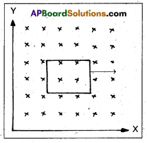
A square loop of side 12 cm with its sides parallel to X and Y axes is moved with a velocity of 8 cm s-1 in the positive x-direction in an environment containing a magnetic field in the positive z-direction. The field is neither uniform in space nor constant in time. It has a gradient of 10-3 T cm-1 along the negative x-direction (that is it increases by 10-3 T cm-1 as one moves in the negative x-direction), and it is decreasing in time at the rate of 10-3 Ts-1. Determine the direction and magnitude of the induced current in the loop if its resistance is 4.50 mΩ.
Solution:
Given, side of loop a = 12 cm
∴ Area of loop (A) = a2 = (12)2 = 144 cm2 = 144 × 10-4 m2 (∵ Area of square = (side)2)
Velocity v = 8 cm/s = 8 × 10⁻² m/s.
Rate of change of magnetic field with distance \(\frac{\mathrm{dB}}{\mathrm{dx}}\) = 10-3 T/cm
Rate of change of magnetic field with time \(\frac{\mathrm{dB}}{\mathrm{dt}}\) = 10-3 T/s
Resistance of the loop R = 4.5 mΩ = 4.5 × 10⁻³Ω
Rate of change of magnetic flux with respect to time
\(\frac{\mathrm{d} \phi}{\mathrm{dt}}\) = \(\frac{\mathrm{d}(\mathrm{BA})}{\mathrm{dt}}\) = \(\left(\frac{\mathrm{dB}}{\mathrm{dt}}\right) \mathrm{A}\) = 10-3 × 144 × 10-4
= 1.44 × 10⁻⁵ Wb/s
Rate of change of magnetic flux due to the motion of loop
\(\frac{\mathrm{d} \phi}{\mathrm{dt}}\) = \(\frac{\mathrm{dB}}{\mathrm{dx}} \cdot \mathrm{A} \cdot \frac{\mathrm{dx}}{\mathrm{dt}}\) = 10-3 × 144 × 10-4 × 8 = 11.52 × 10⁻⁵ Wb/s
Both of the effects cause a decrease in magnetic flux along the positive z-direction.
Total induced emf in the loop e = 1.44 × 10⁻⁵ + 11.52 × 10⁻⁵
e = 12.96 × 10⁻⁵ V
Induced current in the loop = \(\frac{\mathrm{e}}{\mathrm{R}}\) = \(\frac{12.96 \times 10^{-5}}{4.5 \times 10^{-3}}\) = 2.88 × 10⁻²A.
The direction of induced current is such as to increase the flux through the loop along positive z-direction.
Question 3.
It is desired to measure the magnitude of field between the poles of a powerful loud speaker magnet. A small flat search coil of area 2 cm2 with 25 closely wound turns, is positioned normal to the field direction and then quickly snatched out of the field region. Equivalently, one can give it a quick 90° turn to bring its plane parallel to the field direction). The total charge flown in the coil (measured by a ballistic galvanometer connected to coil) is 7.5 mC. The combined resistance of the coil and the galvanometer is 0.50Ω Estimate the field strength of magnet.
Solution:
Area of coil A = 2cm2 = 2 × 10⁻⁴ m2, Number of turns N = 25
Total charge in the coil θ = 7.5 mC (1 mC = 10-3 C) = 7.5 × 10⁻³ C
Resistance of coil R = 0.5Ω
When the coil is removed from the field, the flux is zero ϕf = 0. Induced current in the coil
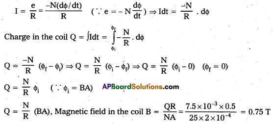
Thus, the strength of magnetic field is 0.75 T.
![]()
Question 4.
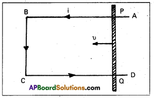
Following figure shows a metal rod PQ resting on the smooth rails AB and positioned between the poles of a permanent magnet. The rails, the rod and the magnetic field are in three mutual perpendicular directions. A galvanometer G connects the rails through a switch K. Length of the rod = 15 cm, B = 0.50 T, resistance of the closed loop containing the rod = 9.0 mΩ. Assume the field to be uniform.
(a) Suppose K is open and the rod is moved with a speed of 12 cm s-1 in the direction shown. Give the polarity and magnitude of the induced emf.
(b) Is there an excess charge built up at the ends of the rods when K is open ? What if K is closed ?
(c) With K open and the rod moving uniformly, there is no net force on the electrons in the rod PQ even though they do experience magnetic force due to the motion of the rod. Explain.
(d) What is the retarding force on the rod when K is closed ?
(e) How much power is required (by an external agent) to keep the rod moving at the same speed (= 12 cm s-1) when K is closed ? How much power is required when K is open ?
(f) How much power is dissipated as heat in the closed circuit ? What is source of this power ?
(g) What is the induced emf in the moving rod if the magnetic field is parallel to the rails instead of being perpendicular ?
Solution:
Given, length of the rod l = 15 cm = 15 × 10-2, Magnetic field B = 0.50 T
Resistance of the closed – loop containing the rod, R = 9mΩ ⇒ 9 × 10⁻³Ω
Velocity of rod V = 12 cm/s = 12 × 10-2 m/s,
a) The magnitude of the motional emf
e = BVl = 0.50 × 12 × 10-2 × 15 × 10-2, e = 9 × 10⁻³ V.
According to the Fleming’s left hand rule, the direction of Lorentz force (f = -e(V × B)) on electrons in PQ is from P to Q. So, p would acquire positive charge and Q would acquire negative charge.
b) Yes, an excess positive charge developes at P and the same amount of negative charge developes at Q as the key is open. When the key K is closed, the induced current flows and maintains the excess charge.
c) When key is open, there is no net force on the electrons because the presence of excess charge at P and Q sets up an electric field and magnetic force on the electrons is balanced by force on them due to force by the electric field. So, there is no net force on the rod.
d) When the key K is closed, current flow in the loop and the current carrying wise experience a retarding force in the magnetic field which is given by
Force = BIl = B . \(\frac{\mathrm{e}}{\mathrm{R}}\) . l = \(\frac{0.5 \times 9 \times 10^{-3} \times 15 \times 10^{-12}}{9 \times 10^{-3}}\) = 7.5 × 10⁻² N.
e) To keep the rod moving at the same speed the required power
= retarding force × velocity = 7.5 × 10-2 × 12 × 10-2 = 9 × 10⁻³ W
f) Power dissipated in closed circuit due to flow of current = I2R
= \(\left(\frac{\mathrm{e}}{\mathrm{R}}\right)^2\) × R = \(\frac{\left(9 \times 10^{-3}\right)^2}{9 \times 10^{-3}}\) = 9 × 10⁻³ W2 The source of this power is the external agent.
g) When the field is parallel to length of rails θ = 0°, induced emf = e = BVl sin θ = 0 (∵ sin θ° = 0). In this situation, the moving rod will not cut the field lines so that flux change is zero and hence induced emf is zero.
Question 5.
An air-cored solenoid with length 30 cm, area of cross-section 25 cm2 and number of turns 500, carries a current of 2.5 A. The current is suddenly switched off in a brief time of 10-3s. How much is the average back emf induced across the ends of the open switch in the circuit? Ignore the variation in magnetic field near the ends of the solenoid.
Solution:
Given, length of solenoid I = 30 cm = 30 × 10-2 m
Area of cross-section A = 25 cm2 = 25 × 10-4 m2
Number of turns N = 500, Current I1 = 2.5A, I2 = 0, Brief time dt = 10-3s.
Induced emf in the solenoid e = \(\frac{\mathrm{d} \phi}{\mathrm{dt}}\) = \(\frac{\mathrm{d}(\mathrm{BA})}{\mathrm{dt}}\) (∵ ϕ = BA)
Magnetic field induction B at a point well inside the long solenoid carring current I is
Question 6.
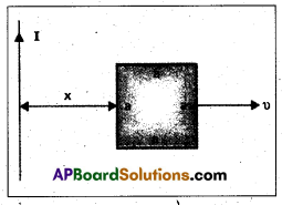
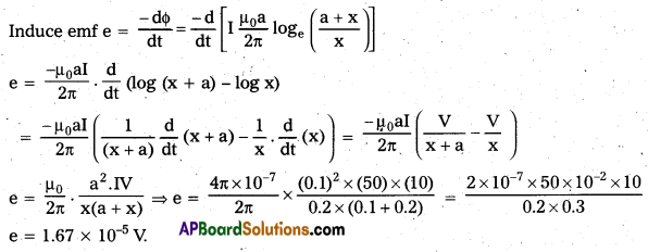
Obtain an expression for the mutual inductance between a long straight wire and a square loop of side a as shown in the figure.
(b) Now assume that the straight wire carries a current of 50 A and the loop is moved to the right with a constant velocity, υ = 10 m/s. Calculate the induced emf in the loop at the instant when x = 0.2 m.
Take α = 0.1 m and assume that the loop has a large resistance.
Solution:
a) Let us assume that an elementary strip of width dx a at distance x from the wire carring current I.
Side of square = a.
The magnetic field due to current carring wire at a distance x from the wire is
B = \(\frac{\mu_0}{4 \pi} \cdot \frac{2 I}{x}\) —— (i)
Small amount of magnetic flux associated with the strip
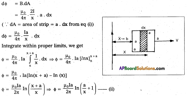
As we know that ϕ = MI —— (iii)
where, M is mutual inductance. From equations (ii) and (iii) we get
This is mutual inductance between wire and square loop.
b) Given current I = 50 A, Velocity V = 10 m/s, x = 0.2 m and a = 0.1 m
Question 7.
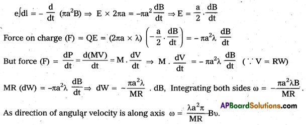
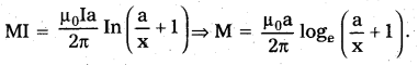
A line charge λ per unit length is lodged uniformly onto the rim of a wheel of mass M and radius R. The wheel has light non-conducting spokes and is free to rotate without friction about its axis (figure). A uniform magnetic field extends over a circular region within the rim. It is given by,
B = B0k (r ≤ a, a < R)
= 0 (otherwise)
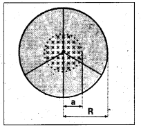
What is the angular velocity of the wheel after the field is suddenly switched off?
Solution:
Given Linear charge density
![]()
Radius of rim = R,
Mass of rim = M,
Magnetic field extends over a circular region
B = -B0 (r ≤ a, a < R) = O (otherwise).
Let the angular velocity of the wheel be w, then induced emf e = \(\frac{-\mathrm{d} \phi}{\mathrm{dt}}\)
E exist along circumference of radius a due to change in magnetic flux.