Andhra Pradesh BIEAP AP Inter 2nd Year Physics Study Material 10th Lesson Alternating Current Textbook Questions and Answers.
AP Inter 2nd Year Physics Study Material 10th Lesson Alternating Current
Very Short Answer Questions
Question 1.
A transformer converts 200 V ac into 2000 V ac. Calculate the number of turns in the secondary if the primary has 10 turns. (A.P. Mar.’19; T.S. Mar. ’16 )
Answer:
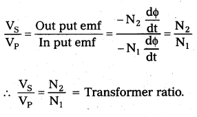
\(\frac{\mathrm{V}_{\mathrm{s}}}{\mathrm{V}_{\mathrm{p}}}\) = \(\frac{N_s}{N_p}\)
Vp = 200V, Vs = 2000V, Np = 10
Ns = \(\frac{\mathrm{V}_{\mathrm{s}}}{\mathrm{V}_{\mathrm{p}}} \times \mathrm{N}_{\mathrm{p}}\) = \(\frac{2000}{200} \times 10\)
Ns = 100.
Question 2.
What type of transformer is used in a 6V bed lamp ?
Answer:
Step down transformer is used in 6V bed lamp.
![]()
Question 3.
What is the phenomenon involved in the working of a transformer ? (T.S. Mar.19; A.P. Mar. 16, Mar. 14)
Answer:
Transformer works on the principle of mutual induction.
Question 4.
What is transformer ratio ?
Answer:
The ratio of secondary e.m.f to the primary e.m.f. (or) number of turns in secondary to the number of turns in the primary is called the transformer ratio.
Transformer ratio = \(\frac{V_s}{V_p}\) = \(\frac{N_s}{N_p}\).
Question 5.
Write the expression for the reactance of
- an inductor and
- a capacitor.
Answer:
- Inductive reactance (XL) = ωL
- Capacitive reactance (XC) = \(\frac{1}{\omega C}\)
Question 6.
What is the phase difference between A.C emf and current in the following: Pure resistor, pure inductor and pure capacitor.
Answer:
- In pure resistor A.C. e.in.f and current are in phase with each other.
- In pure inductor, current lags behind the e.m.f. by an angle of \(\frac{\pi}{2}\) (or) 90°.
- In pure capacitor, current leads the e.m.f by an angle \(\frac{\pi}{2}\) (or) 90°.
Question 7.
Define power factor. On which factors does power factor depend ?
Answer:
The ratio of true power and apparent power (virtual power) in an a.c circuit is called as power factor of the circuit.
Power factor (cosϕ) = \(\frac{\mathrm{P}}{\mathrm{P}_{\mathrm{rms}}}\). (∴ Prms = VrmsIrms)
Power factor depends on r.m.s voltage, r.m.s current and average power (P).
Question 8.
What is meant by wattless component of current ?
Answer:
Average power (P) = Vrms(Irms sinϕ)cos \(\frac{\pi}{2}\)
The average power consumed in the circuit due to Irms sin ϕ) component of current is zero. This component of current is known as wattless current. (Irms sin ϕ) is the wattless component of current.
Question 9.
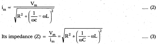
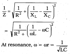
When does a LCR series circuit have minimum impedance?
Answer:
In LCR series circuit, Impedance (Z) = \(\sqrt{R^2+\left(\frac{1}{\omega C}-\omega L\right)^2}\)
At a particular frequency, ωL = \(\frac{1}{\omega C}\)
The impedance is minimum (Z = R)
This frequency is called resonant frequency
![]()
Question 10.
What is the phase difference between voltage and current when the power factor in LCR series circuit is unity ?
Answer:
In LCR series circuit power factor (cos ϕ) = 1
∴ Phase difference between voltage and current is zero. (ϕ = 0)
Short Answer Questions
Question 1.
Obtain an expression for the current through an inductor when an AC emf is applied.
Answer:
Circuit consists of pure inductor of inductance L. Let an ac e.m.f V = Vm sin ωt is applied to it. Let i be the instantaneous current.
Back e.m.f developed across the inductor = -L\(\frac{\mathrm{di}}{\mathrm{dt}}\)
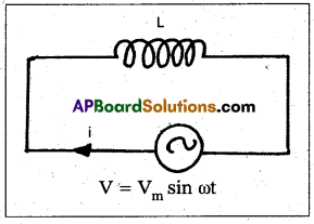
Total e.m.f = Vm sin ωt – L\(\frac{\mathrm{di}}{\mathrm{dt}}\) ——- (1)
According to ohms law this must be equal to iR = 0
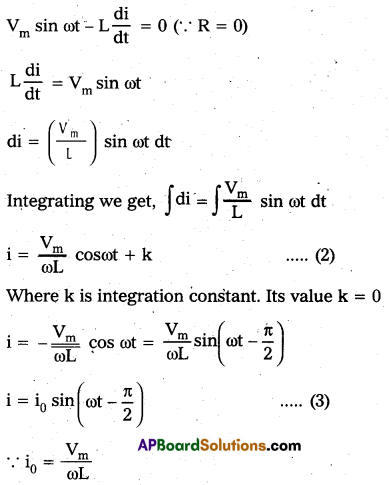
This is the expression for the instantaneous current through inductor. Here current lags behind the e.m.f by \(\frac{\pi}{2}\) radian (or) 90°.
Question 2.
Obtain an expression for the current in a capacitor when an AC emf is applied.
Answer:
Circuit consists of pure capacitor of capacitance C. Let an A.C emf V = Vm sin ωt is applied to it. Let i and q be the instantaneous values of current and charge.
Potential difference across capacitor = –\(\frac{\mathrm{q}}{\mathrm{C}}\).
Total emf = Vm sin ωt –\(\frac{\mathrm{q}}{\mathrm{C}}\)
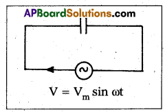
According to Ohms law this must be equal to iR = 0
Vm sin ωt –\(\frac{\mathrm{q}}{\mathrm{C}}\) = 0
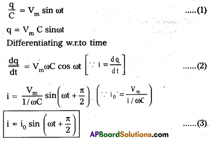
i0 is peak value of current. Here the current leads the applied e.m.f. by \(\frac{\pi}{2}\) or (or) 90°
![]()
Question 3.
State the principle on which a transformer works. Describe the working of a transformer with necessary theory.
Answer:
Transformer is a device to convert a low alternating current of high voltage into high alternating current of low voltage and vice versa.
Principle : It works on the principle of mutual induction between two coils.
Working : When an alternating emf is applied across the primary coil, the input voltage changes with time. Hence the magnetic flux through the primary also changes with time.
This changing magnetic flux will be linked with secondary through the core. An emf is induced in the secondary.
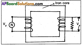
Theory: Let N1 and N2 be the number of turns in the primary and secondary. Let VP and Vs be the emf s across the primary and secondary.
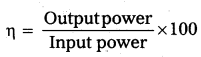
Efficiency of transformer:
It is the ratio of output power to the input power.
Long Answer Questions
Question 1.
Obtain on expression for impedance and current in series LCR circuit. Deduce an expresssion for the resonating frequency of an LCR series resonating circuit
Answer:
Circuit consists of resistor of resistance R, inductor of inductance L and capacitor of capacitance C connected in series with an a.c Voltage V = Vm sin ωt.
Let i be the current and q be the charge at any instant t.
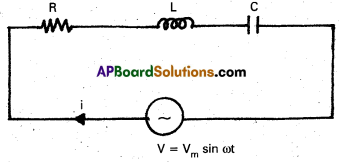
Back e.m.f across inductor is -L\(\frac{\mathrm{di}}{\mathrm{dt}}\)
and across capacitor is \(\frac{-\mathrm{q}}{\mathrm{C}}\)
Total e.m.f = Vm sin ωt – L\(\frac{\mathrm{di}}{\mathrm{dt}}\) – \(\frac{\mathrm{q}}{\mathrm{C}}\)
According to Ohms law, this must be equal to iR
Vm sinωt – L\(\frac{\mathrm{di}}{\mathrm{dt}}\) – \(\frac{q}{C}\) = iR
L\(\frac{\mathrm{di}}{\mathrm{dt}}\) + iR + \(\frac{q}{C}\) = Vm sin ωt ——- (1)
The current i any instant in the circuit is
i = im sin(ωt – ϕ) if ωL > \(\frac{1}{\omega \mathrm{C}}\) which is possible at high frequencies.
i = im sin (ωt + ϕ) if ωL which is possible at low frequencies.
The maximum current (im) is given by
Let ϕ be the phase difference between current and e.m.f
Resonant frequency(f0):
At this frequency, the impedance of LCR circuit is minimum and is equal to R. At this frequency current is maximum This frequency is called resonant frequency (f0).
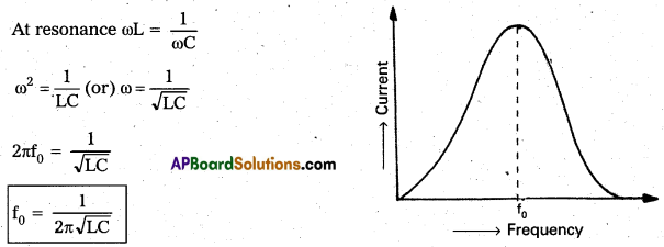
In frequency response curve, at resonant frequency (f0), current is maximum. This series resonant circuit is called acceptor circuit.
Problems
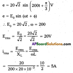
Question 1.
An ideal inductor (no internal resistance for the coil) or 20 mH is connected in series with an AC ammeter to an AC source whose emf is given by e = 20\(\sqrt{2}\) sin(200t + π/3)V, where t is in seconds. Find the reading of the ammeter ?
Solution:
Given that L = 20 mH = 20 × 10-3H
Question 2.
The instantaneous current and instantaneous voltage across a series circuit containing resistance and inductance
are given by i = \(\sqrt{2}\) sin (100t – π/4)A and υ = 40 sin (100t) V. Calculate the resistance ?
Solution:
i = \(\sqrt{2}\) sin (100t – π/4)A
(∵ i = i0 sin(ωt – ϕ))
υ = 40 sin (100t)V (∵ V = V0sin(ωt))
i0 = \(\sqrt{2}\), V0 = 40, ω = 100, ϕ = π/4
R = \(\frac{\mathrm{V}_0}{\mathrm{i}_0} \cos \phi\) = \(\frac{40}{\sqrt{2}} \cos \frac{\pi}{4}\)
R = \(\frac{40}{\sqrt{2}} \times \frac{1}{\sqrt{2}}\)
R = 20Ω
Question 3.
In an AC circuit, a condenser, a resistor and a pure inductor are connected in series across an alternator (AC generator). If the voltages across them are 20 V, 35 V and 20 V respectively, find the voltage supplied by the alternator.
Solution:
VC = 20V, VR = 35V, VL = 20V
V = \(\sqrt{\mathrm{V}_{\mathrm{R}}^2+\left(\mathrm{V}_{\mathrm{L}}^2-\mathrm{V}_{\mathrm{C}}^2\right)}\)
V = \(\sqrt{(35)^2+\left(20^2-20^2\right)}\)
V = \(\sqrt{35^2}\)
V = 35 Volt.
Question 4.
An AC circuit contains a resistance R, an inductance L and a capacitance C connected in series across an alternator of constant voltage and variable frequency. At resonant frequency, it is found that the inductive reactance, the capacitive reactance and the resistance are equal and the current in the circuit
is i0. Find the current in the circuit at a frequency twice that of the resonant frequency.
Solution:
At Resonance R = ω0L = \(\frac{1}{\omega_0 C}\)

![]()
Question 5.
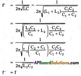
A series resonant circuit contains L1, R1 and C1. The resonant frequency is f. Another series resonant circuit contains L2, R2 and C2. The resonant frequency is also f. If these two circuits are connected in series, calculate the resonant frequency.
Solution:
Given that resonant frequency (f)
= \(\frac{1}{2 \pi \sqrt{\mathrm{L}_1 C_1}}\) = \(\frac{1}{2 \pi \sqrt{\mathrm{L}_2 \mathrm{C}_2}}\)
L1C1 = L2C2
L1 = \(\frac{\mathrm{L}_2 \mathrm{C}_2}{\mathrm{C}_1}\) —— (1)
When these two circuits are connected in series
The total inductance L = L1 + L2
Total capacitance is given by
\(\frac{1}{\mathrm{C}}\) = \(\frac{1}{C_1}\) + \(\frac{1}{C_2}\) (or) C = \(\frac{\mathrm{C}_1 \mathrm{C}_2}{\mathrm{C}_1+\mathrm{C}_2}\)
The resonant frequency of combined circuit is given by
Question 6.
In a series LCR circuit R = 200Ω and the voltage and the frequency of the mains supply is 200 V and 50 Hz respectively. On taking out the capacitance from the circuit the current lags behind the voltage by 45°. On taking out the inductor from the circuit the current leads the voltage by 45°. Calculate the power dissipated in the LCR circuit.
Solution:
R = 200Ω, V = 200V, f = 50Hz
ϕ = 45°, At resonance ωL = \(\frac{1}{\omega \mathrm{C}}\)
Power dissipated (P) = Vi = \(\frac{\mathrm{V}^2}{\mathrm{R}}\) (∵ i = \(\frac{V}{R}\))
P = \(\frac{(200)^2}{200}\) = 200ω
Question 7.
The primary of a transformer with primary to secondary turns ratio of 1: 2, is connected to an alternator of voltage 200 V. A current of 4A is flowing though the primary coil. Assuming that the transformer has no losses, find the secondary voltage and current are respectively.
Solution:
Given that \(\frac{\mathbf{N}_1}{\mathbf{N}_2}\) = \(\frac{1}{2}\)
E1 = 200V, i1 = 4A
i)
Transformer ratio = \(\frac{E_2}{E_1}\) = \(\frac{\mathrm{N}_2}{\mathrm{~N}_1}\)
\(\frac{E_2}{200}\) = \(\frac{2}{1}\)
E2 = 400V
ii)
\(\frac{\mathrm{N}_2}{\mathrm{~N}_1}\) = \(\frac{i_1}{i_2}\)
\(\frac{2}{1}\) = \(\frac{4}{i_2}\)
i2 = 2A
Textual Exercises
Question 1.
A 100Ω resistor is connected to a 220 V. 50 Hz ac supply.
(a) What is the rms value of current in the circuit ?
(b) What is the net power consumed over a full cycle ?
Solution:
Given resistance R = 100Ω
Vrms = 220V
Frequency f = 50Hz
a) Current in the circuit
Irms = \(\frac{V_{r m s}}{R}\) = \(\frac{220}{100}\) = 2.2A
b) Net power consumed in full cycle
P = Vrms × Irms
= 220 × 2.2
= 474 W
Question 2.
(a) The peak voltage of an ac supply is 300 V. What is the rms voltage ?
(b) The rms value of current in an ac circuit is 10A. What is the peak current ?
Solution:
a) Given, peak value of voltage V0 = 300V
The rms value of current Irms = 10A
The rms value of voltage
Vrms = \(\frac{\mathrm{V}_0}{\sqrt{2}}\) = \(\frac{300}{\sqrt{2}}\) = 212.1V
b) Using the formula
Irms = \(\frac{\mathrm{I}_0}{\sqrt{2}}\)
The peak value of current
I0 = \(\sqrt{2} \times \mathrm{I}_{\mathrm{rms}}\)
= \(\sqrt{2}\) × 10 = 1.414 × 10
I0 = 14.14 A
Question 3.
A 44 mH inductor is connected to 220 V, 50 Hz ac supply. Determine the rms value of current in the circuit.
Solution:
Given inductance
L = 44mH = 44 × 10-3H
Vrms = 220V
Frequency of Inductor f = 50Hz
Inductive resistance XL = 2πfL
= 2 × 3.14 × 50 × 44 × 10-3
= 13.83Ω
The rms value of current in the circuit
Irms = \(\frac{V_{\text {rms }}}{X_L}\) = \(\frac{220}{13.83}\)15.9A
Question 4.
A 60 μF capacitor is connected to a 110V, 60 Hz ac supply. Determine the rms value of the current in the circuit.
Solution:
Given, capacitance of the capacitor C
= 60μF
= 60 × 10-6F
Vrms = 110
Frequency of AC supply f = 60Hz
Capacitive reactance
XC = \(\frac{1}{2 \pi \mathrm{fC}}\) = \(\frac{1}{2 \times 3.14 \times 60 \times 60 \times 10^{-6}}\)
= 44.23Ω
The rms value of current in the circuit
Vrms = \(\frac{\mathrm{V}_{\mathrm{rms}}}{\mathrm{X}_{\mathrm{C}}}\) = \(\frac{110}{44.23}\) = 2.49A
![]()
Question 5.
In Exercises 3 and 4, what is the net power absorbed by each circuit over a complete cycle. Explain your answer.
Solution:
In Exercise 3 Average power P = Vrms, Irms. cos ϕ
As we know that the phase difference between current and voltage in case of inductor is 90°.
P = Vrms. Irms. cos 90° = 0
In Exercise 4 Average power
P = Vrms. Irms. cos ϕ
We know that the phase difference between current and voltage in case of capacitor is 90°
P = Vrms. Irms. cos 90° = 0
Question 6.
Obtain the resonant frequency ωr of a series LCR circuit with L = 2.0H. C = 32 μF and R = 10Ω. What is the Q-value of this circuit ?
Solution:
Given, L = 2H, C = 32μF, R = 10Ω
Resonant angular frequency
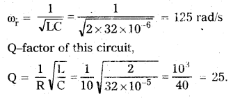
Question 7.
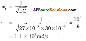
A charged 30 μF capacitor is connected to a 27 mH inductor. What is the angular frequency of free oscillations of the circuit ?
Solution:
Capacitance of capacitor C = 30μF = 30 × 10-6F
Inductance L = 27mH = 27 × 10-3H
For free oscillations, the angular frequency should be resonant frequency. Resonant angular frequency of oscillation of the circuit
Question 8.
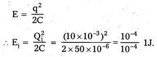
Suppose the initial charge on the capacitor in Exercise 7 is 6 mC. What is the total energy stored in the circuit initially ? What is the total energy at later time ?
Answer:
Given, charge on the capacitor Q = 6mC = 6 × 10⁻³
C = 30μF = 30 × 10-6F
Energy stored in the circuit
E = \(\frac{Q^2}{2 C}\) = \(\frac{\left(6 \times 10^{-3}\right)^2}{2 \times 30 \times 10^{-2}}\) = \(\frac{36}{60}\) = 0.6J
After some time, the energy is shared between C and L, but the total energy remains constant.
So, we assume that there is no loss of energy.
Question 9.
A series LCR circuit with R = 20Ω, L = 1.5 H and C = 35µF is connected to a variable-frequency 200 V ac supply. When the frequency of the supply equals the natural frequency of the circuit, what is the average power transferred to the circuit in one complete cycle ?
Given resistance R = 200Ω
Inductance L = 1.5H, capacitance C = 35µF = 35 × 10-6F and voltage Vrms = 200V
When, the frequency of the supply equal to the natural frequency of the circuit, this is the condition of resonance. At the condition of resonance, Impedance Z = R = 20Ω
The rms value of current in the circuit
Irms = \(\frac{V_{r m s}}{Z}\) = \(\frac{200}{20}\) = 10A
ϕ = 0°
Power transferred to the circuit in one complete cycle.
P = Irms Vrms cos ϕ
= 10 × 200 × cos0° = 2000 ω = 2Kω
Question 10.
A radio can tune over the frequency range o a portion of MW broadcast band: (800 kHz to 1200 kHz). If its LC circuit has an effective inductance of 200 μH, what must be the range of its variable capacitor?
(Hint: For tuning, the natural frequency i.e., the frequency of free oscillations of the LC circuit should be equal to the frequency of the radiowave.)
Solution:
Given, minimum frequency
f1 = 800KHz = 8 × 10⁵HZ
Inductance
L = 200μH = 200 × 10-5H = 2 × 10⁻⁴H.
Maximum frequency
f2 = 1200 KHz = 12 × 105Hz for tuning, the natural frequency is equal to the frequency of oscillations that means it is the case of resonance.
Frequency of oscillations f = \(\frac{1}{2 \pi \sqrt{L C}}\)
For capacitance C1, f1 = \(\frac{1}{2 \pi \sqrt{L C_i}}\)
C1 = \(\frac{1}{4 \pi^2 \mathrm{f}_1^2 \mathrm{~L}}\)
= \(\frac{1}{4 \times 3.14 \times 3.14 \times\left(8 \times 10^5\right)^2 \times 2 \times 10^{-4}}\)
= 197.7 × 10⁻¹²F
= 197.7PF
for capacitance C2, f2 = \(\frac{1}{2 \pi \sqrt{L C_2}}\)
C2 = \(\frac{1}{4 \pi^2 f_1^2 \mathrm{C}}\)
= \(\frac{1}{4 \times 3.14 \times 3.14 \times\left(12 \times 10^5\right)^2 \times 2 \times 10^{-4}}\)
= 87.8 × 10⁻¹²F = 87.8pF
Thus, the range of capacitor is 87.8pF to 197.7pF.
Question 11.
Figure shows a series LCR circuit connected to a variable frequency 230 V source. L = 5.0 H, C = 80μF, R = 40Ω.
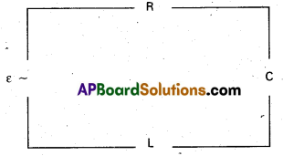
(a) Determine the source frequency which drives the circuit in resonance.
(b) Obtain the impedance of the circuit and the amplitude of current at the resonating frequency.
(c) Determine the rms potential drops across the three elements of the circuit. Show that the potential drop across the LC combination is zero at the resonating frequency.
Solution:
Given, the rms value of voltage
Vrms = 230V
Inductance L = 5H
Capacitance C = 80μf = 80 × 10-6F
Resistance R = 40Ω
a) For resonance frequency of circuit
ωr = \(\frac{1}{\sqrt{\mathrm{LC}}}\) = \(\frac{1}{\sqrt{5 \times 80 \times 10^{-6}}}\) = 50 rad/s
Source frequency at resonance, then
υ0 = \(\frac{\omega_0}{2 \pi}\) = \(\frac{50}{2 \times 3.14}\) = 7.76 Hz
b) At the resonant frequency, XL = XC
So, impedance of the circuit Z = R
∴ Impedance Z = 40Ω
The rms value of current in the circuit
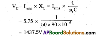
Irms = \(\frac{V_{r m s}}{Z}\) = \(\frac{230}{40}\) = 5.75A
Amplitude of current I0 = Irms\(\sqrt{2}\)
= 5.75 × \(\sqrt{2}\)
= 8.13A
c) The rms potential drop across L
VL = Irms XL
= Irms ωrL = 5.75 × 50 × 5 = 1437.5V
The rms potential drop across R
VR = Irms = R = 5.75 × 40 = 230V
The rms potential drop across C,
Potential drop across LC combinations
= Irms(XL – XC)
= Irms(XL – XL) = 0 (∵ XL – XC)
Additional Exercises
Question 1.
An LC circuit contains a 20 mH inductor and a 50μF capacitor with an initial charge of 10 mC. The resistance of the circuit is negligible. Let the instant the circuit is closed be t = 0.
(a) What is the total energy stored initially ? Is it conserved during LC oscillations ?
(b) What is the natural frequency of the circuit ?
(c) At What time is the energy stored
(i) Completely electrical (i.e., stored in the capacitor) ?
(ii) completely magnetic (i.e., stored in the inductor) ?
(d) At what times is the total energy shared equally between the inductor and the capacitor ?
(e) As a resistor is inserted in the circuit, how much energy is eventually dissipated as heat ?
Solution:
Given Inductance L = 20mH = 20 × 10-3H
Capacitance of capacitor
C = 50μf = 50 × 10-6F
Initial charge on the capacitor,
Qi = 10mc = 10 × 103C
a) The total energy stored across the capacitor initially,
Yes, this energy is conserved during LC oscillations.
b) To get the natural frequency or resonant frequency,
fr = \(\frac{1}{2 \pi \sqrt{L C}}\)
= \(\frac{1}{2 \times 3.14 \times \sqrt{20 \times 10^{-3} \times 50 \times 10^{-6}}}\)
= \(\frac{7 \times 10^3}{44}\) = 159.2 Hz.
The natural frequency of the circuit
ω = 2πV = 2π × 159.2
= 999.78 ≈ 1000 = 103 rad/s
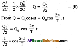
c)
i) Let at any instant the energy stored is completely electrical the charge on the capacitor Q = Q0 cos ωt
Q = Q0 cos \(\frac{2 \pi}{T} \cdot t\) —– (1)
Q is maximum as it is equal to Q0, only if cos \(\frac{2 \pi}{T}\) t = ±1 = cosnπt or t
= \(\frac{\mathrm{nT}}{2}\), where n = 1, 2, 3. ..
t = 0, T/2, T, 3T/2, ………..
Thus, the energy stored is completely electrical at t = 0, T/2, T, 3/2……….
ii) Let at any instant, the energy stored is completely magnetic as when the electrical energy across the capacitor is zero.
q = 0
Q = Q0cos \(\frac{2 \pi t}{T}\) = 0 (from eq(i))
∴ cos \(\frac{2 \pi}{T} \cdot t\) = 0 = \(\frac{\mathrm{n} \pi}{2}\) or t = \(\frac{\mathrm{nT}}{4}\) = cos.
It happens if t = T/4, 3T/4, \(\frac{\mathrm{5T}}{4}\),………..
Thus, the energy stored is completely magnetic at
t = T/4, 3T/4, 5T/4………..
d) Equal sharing of energy between inductor and capacitor means the energy stored in capacitor = \(\frac{1}{2}\) × Maximum energy
or cos(2n + 1)π/4 = cos \(\frac{2 \pi \mathrm{t}}{\mathrm{T}}\)
\(\frac{(2 n+1) \pi}{4}\) = \(\frac{2 \pi t}{T}\)
t = T/8(2n + 1) (n = 0, 1, 2, 3, ……..)
Hence the energy will be shared half on capacitor and half on inductor.
t = \(\frac{T}{8}\), \(\frac{3 \mathrm{~T}}{8}\), \(\frac{5 \mathrm{~T}}{8}\), ………..
e) As a resistor is inserted in the circuit, all of the energy loss during heating. Energy loss = 1J. The oscillations becomes damped and becomes disappear after sometime as the total energy loss in the form of heat.
![]()
Question 2.
A coil of inductance 0.50 H and resistance 100Ω is connected to a 240 V, 50Hz ac supply.
a) What is the maximum current in the coil ?
b) What is the time lag between the voltage maximum and the current maximum ?
Solution:
Given, Inductance L = 0.50H
Resistance R = 100Ω
The rms value of voltage
Vrms = 240V, f = 50Hz
a) Impedance of circuit
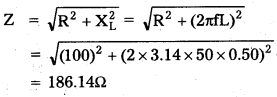
the rms value of current
Irms = \(\frac{\mathrm{V}_{\mathrm{rms}}}{\mathbf{Z}}\) = \(frac{240}{31400.15}\) = 0.00764
the maximum value of current in the circuit
I0 = \(\sqrt{2}\) Irms = 1.414 × 0.00764 = 1.824A
b) Using the formula of time lag,
t = \(\frac{\phi}{\omega}\)
tan ϕ = \(\frac{X_L}{R}\) = \(\frac{\omega \mathrm{L}}{\mathrm{R}}\) = \(\frac{2 \pi \mathrm{fL}}{\mathrm{R}}\) = \(\frac{2 \times 3.14 \times 50 \times 0.50}{100}\)
ϕ = tan-6(1.571) = 57.5
![]()
Time lag t = \(\frac{\phi}{\omega}\) = \(\frac{57.5 \pi}{180 \times 2 \pi \mathrm{f}}\)
= \(\frac{57.5}{180 \times 2 \times 50}\)
= 3.19 × 10⁻³S
Thus, the time lag between the voltage maximum and the current maximum is 3.19 × 10⁻³S
Question 3.
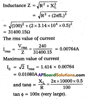
Obtain the answers (a) to (b) in Exercise 13 if the circuit is connected to a high frequency supply (240V, 10 kHz). Hence, explain the statement that at very high frequency an inductor in a circuit nearly amounts to an open circuit. How does an inductor behave in a dc circuit after the steady state?
Answer:
Given frequency f = 10kHz = 104Hz
the rms value of voltage Vrms = 240v
from Exercise 13
Resistance R = 100Ω
Inductance L = 0.5H
Question 4.
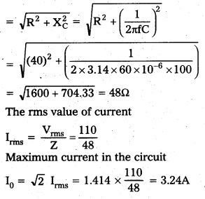
A 100μF capacitor in series with a 40Ω resistance is connected to a 110V. 60 Hz supply.
(a) What is the maximum current in the circuit?
(b) What is the time lag between the current maximum and the voltage maximum?
Answer:
Given capacitance of capacitor
C = 100µF= 100 × 10-6F
Resistance R = 40Ω
the rms value of voltage Vrms = 110V
Frequency f = 60Hz
(a) Impedance Z
(b) Time lag (t) = \(\frac{\phi}{\omega}\)
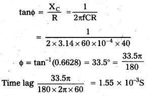
Thus, the time lag between the voltage maximum and the current maximum is 1.55 × 10⁻³S.
Question 5.
Obtain the answers to (a) and (b) in Exercise 15 if the circuit is connected to a 110 V, 12 kHz supply? Hence, explain the statement that a capacitor is a conductor at very high frequencies. Compare this behaviour with that of a capacitor in a dc circuit after the steady state.
Answer:
Given, the rms value of voltage,
Vrms = 110V
The frequency of capacitor
f = 12kHz = 12000 Hz.
Capacitance of conductor C = 10-4F.
Resistance R = 40Ω
Capacitive Resistance
XC = \(\frac{1}{2 \pi \mathrm{fC}}\) = \(\frac{1}{2 \times 3.14 \times 12000 \times 10^{-4}}\)
= 0.133Ω
The rms value of current
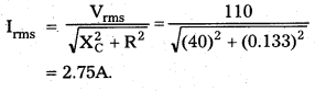
The maximum value of current,
I0 = \(\sqrt{2}\) Irms
= 1.414 × 2.75
= 3.9A
Here, the value of XC is very small, so term containing C is negligible.
tan ϕ = \(\frac{1}{\omega \mathrm{CR}}\)
= \(\frac{1}{2 \times 3.14 \times 12000 \times 10^{-4} \times 40}\)
= \(\frac{1}{96 \pi}\)
It is very very small.
In DC circuits, ω = 0
XC = \(\frac{1}{\omega C}\) = ∞
So, it behaves like an open circuit.
Question 6.
Keeping the source frequency equal to the resonating frequency of the series LCR circuit, if the three elements L, C and R are arranged in parallel, show that the total current in the parallel LCR circuit is minimum at this frequency. Obtain the current rms value in each branch of the circuit for the elements and source specified in Exercise 11 for this frequency.
Solution:
As they are corrected in the parallel combination
\(\frac{1}{Z}\) = \(\frac{1}{R}\) + (\(\frac{1}{X_L}\) + \(\frac{1}{X_C}\))
As the reactance (XC – XL) is perpendicular to the ohmic resistance R, therefore we can write as
That means \(\frac{1}{Z}\) = minimum and thus Z = maximum. As Z is maximum, current will be minimum, current through inductor
Question 7.
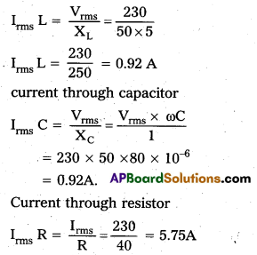
A circuit containing a 80 mH inductor and a 60μF capacitor in series is connected to a 230 V 50 Hz supply. The resistance of the circuit is negligible.
(a) Obtain the current amplitude and rms values.
(b) Obtain the rms values of potential drops across each element.
(c) What is the average power transferred to the inductor?
(d) What is the average power transferred to the capacitor?
(e) What is the total average power absorbed by the circuit? [‘Average’ implies ‘averaged over one cycle’]
Answer:
Given Inductance
L = 80mH = 80 × 10-3H
Capacitance of capacitor
C = 60μF = 60 × 10-6F .
The rms value of voltage
Vrms = 230V
Frequency f = 50Hz; Resistance R = 0
a) Impedance of circuit
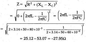
As ZCO, means XL < XC, emf lags by current by 90°
The rms value of current
Irms = \(\frac{\mathrm{V}_{\mathrm{rms}}}{\mathrm{Z}}\) = \(\frac{230}{27.95}\) = 8.29A
The maximum value of current
I0 = \(\sqrt{2} I_{\text {rms }}\) = 1.414 × 8.29 = 11.64A
b) Potentiál drop acrõss L
VrmsL = Irms × XL = 8.29 × 2 × 3.14 × 50 × 80 × 10-3
= 208.25 V
Potential drop across C
VrmsC = Irms × XC
= 8.29 × \(\frac{1}{2 \times 3.14 \times 50 \times 60 \times 10^{-6}}\)
= 440.02 V
∴ Applied rms voltage = VC – VL
= 440 – 208.25 = 231.75V
c) Average power transferred to the inductor
P = Irms Vrms. cosϕ
As the phase difference is 90°, So P = 0
d) Average power transferred to the capacitor.
P = Irms Vrms. cosϕ
As the phase difference is 90°, So P = 0
e) As there is no resistance in the circuit, so average power is equal to sum of average power due to inductor and capacitor. That means the average power consumed is zero.
![]()
Question 8.
Suppose the circuit in Exercise 18 has a resistance of 15Ω. Obtain the average power transferred to each element of the circuit, and the total power absorbed.
Solution:
Given, the rms value of voltage V = 230V
Vrms = 230V
Resistance R = 15Ω
Frequency f = 50Hz
Average power across inductor and capacitor is zero as the phase difference between current and voltage is 90°.
Total power absorbed = power absorbed in resistor, Pav
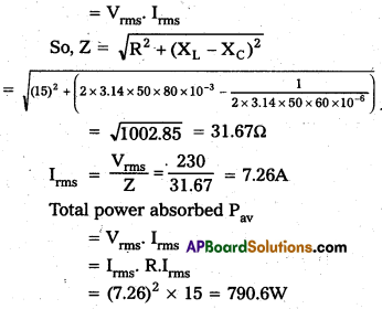
Total power absorbed = 790.6W
Question 9.
A series LCR circuit with L = 0.12 H, C = 480 nF, R = 23Ω is connected to a 230 V variable frequency supply.
a) What is the source frequency for which current amplitude is maximum. Obtain this maximum value.
b) What is the source frequency for which average power absorbed by the circuit is maximum. Obtain the value of this maximum power.
c) For which frequencies of the source is the power transferred to the circuit half the power at resonant frequency ? what is the current amplitude at these frequencies ?
d) What is the Q-factor of the given circuit ?
Answer:
Inductance L = 0.12H,
Capacitance C = 480nF = 480 × 10-9F
Resistance R = 23Ω
The rms value of voltage
Irms = \(\frac{V_{r m s}}{Z}\) = \(\frac{230}{23}\) = 10A
The maximum value of current I0 = \(\sqrt{2}\)
Irms = 1.414 × 10 = 14.14A.
At natural frequency, the current amplitude is maximum.
ω = \(\frac{1}{\sqrt{\mathrm{LC}}} \frac{1}{2 \pi \sqrt{0.12 \times 480 \times 10^{-9}}}\) = 4166.6
= 4167 rad/s
b) Average power is maximum for resonance.
Pav(max) = I2rms R = 10 × 10 × 23 = 2300W.
c) Power transferred to the circuit is half the power at resonant frequency
Δω = \(\frac{\mathrm{R}}{2 \mathrm{~L}}\) = \(\frac{23}{2 \times 0.12}\) = 95.83 rad/s
ΔV = \(\frac{\Delta \mathrm{W}}{2 \pi}\) = 15.2Hz
The frequencies at which power transferred is half .
V = V0 ± ΔV = 663.48 ± 15.26
So, frequencies are 448.3Hz and 678.2Hz, the maximum current
I = \(\frac{\mathrm{I}_0}{\sqrt{2}}\) = \(\frac{14.14}{\sqrt{2}}\) = 10A
d) Q-factor = \(\frac{\omega_{\mathrm{r}}}{\mathrm{R}}\) = \(\frac{4166.7 \times 0.12}{23}\) = 21.74
Question 10.
Obtain the resonant frequency and Q-factor of series LCR circuit with L = 3.0 H, C = 27μF, and R = 10.4Ω. It is desired to improved the sharpness of the resonance of the circuit by reducing its ‘full width at half maximum’ by a factor of 2. Suggest a suitable way.
Solution:
Given, inductance L = 3H
Capacitance of capacitor
C = 27μF = 27 × 10-6F
Resistance R = 7.4Ω
the resonant frequency of circuit
ωr = \(\frac{1}{\sqrt{\mathrm{LC}}}\) = \(\frac{1}{\sqrt{3 \times 27 \times 10^{-6}}}\) = \(\frac{1000}{9}\)
= 111.1 rad/s.
Q-factor of a series LCR circuit
Q-factor = \(\frac{\omega_{\mathrm{r}} \mathrm{L}}{\mathrm{R}}\) = \(\frac{111.1 \times 3}{7.4}\) = 45.04
To reduce the full width at half by factor Q, we have to reduce the value of R as R/2
\(\frac{R}{2}\) = \(\frac{7.4}{2}\) = 3.7Ω
Question 11.
Answer the following questions :
a) In any ac circuit, is the applied Instantaneous voltage equal to the algebraic sum of the instantaneous voltages across the series elements of the circuit ? Is the same true for rms voltage ?
Answer:
Yes, the applied voltage equal to the algebraic sum of the instantaneous voltages across the series elements of the circuit
No, it is not true for rms voltage because there is some phase differences across different elements of circuits.
b) A capacitor is used in the primary circuit of an induction coil.
Answer:
A capacitor is used in the primary circuit of an induction coil because when the circuit is broken, a large induced voltage is used up in charging the capacitor. So, the parking or any damages are avoided.
c) An applied voltage signal consists of a superposition of a dc voltage and an ac voltage of high frequency. The circuit consists of an inductor and a capacitor in series. Show that the dc signal will appear across C and the ac signal across L.
Solution:
As we know that
XC = \(\frac{1}{2 \pi f c}\), XL = 2πfL
f = 0, XC = ∞, XL = 0
d) A choke coil in series with a lamp is connected to a dc line. The lamp is seen to shine brightly. Insertion of an Iron core in the choke causes no change in the lamp’s brightness. Predict the corresponding observations if the connection is to an ac line.
Answer:
When the choke coil is connected to dc, there is no change in the brightness. Because f = 0, XL = 6. So, no change in the brightness. In Ac, the choke offers impedance, so, it glows dim. As we insert an iron core the magnetic field increases and hence inductance increases.
BA = LI = ϕ
L ∝ B
So, XL also increases and the brightness of bulb decreases.
e) Why is choke coil needed in the use of fluorescent tubes with ac mains ? Why can we not use an ordinary resistor instead of the choke coil ?
Answer:
We use the choke coil instead of resistance because the power loss across resistor is maximum while the power loss across choke is zero.
For resistor, ϕ = 0
P = Irms. Vrms. cos ϕ
= Irms. Vrms = maximum
For Inductor ϕ = 90°
P = Irms. Vrms. cos 90° = 0
Question 12.
A power transmission line feeds input power at 2300 V to a stepdown transformer with its primary windings having 4000 turns, what should be the number of turns in the secondary in order to get output power at 230 V ?
Solution:
Given Primary voltage VP = 2300V NP = 4000 turns
Secondary voltage VS = 230V
Using formula,
\(\frac{\mathrm{V}_{\mathrm{S}}}{\mathrm{V}_{\mathrm{P}}}\) = \(\frac{N_S}{N_P}\)
\(\frac{230}{2300}\) = \(\frac{\mathrm{N}_{\mathrm{S}}}{4000}\)
NS = 400
∴ thus, the number of turns in secondary are 400.
![]()
Question 13.
At a hydroelectric power plant, the water, pressure head is at a height of 300 m and the water flow available is 100 m3s-1. If the turbine generator efficiency is 60%, estimate the electric power available from the plant (q = 9.8 ms-2).
Answer:
Given, height of water h = 300m
Rate of flow of water V = 100m3/s
efficiency η = 60%
g = 9.8m/s2.
As we know that input power is required to raised the water up to height
h = 300 m
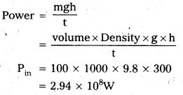
Suppose, the power output is Pout which is equal to the power available from the plant. The efficiency of generator
η = \(\frac{P_{\text {out }}}{P_{\text {in }}}\)
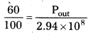
pout = 176.4MW = 1764 × 105W
Question 14.
A small town with a demand of 800 kW of electric power at 220 V is situated 15 km away from an electric plant generating power at 440 V. The resistance of the two wire line carrying power in 0.5 Ω per km. The town gets power from the line through a 4000 – 220V step-down transformer at a substation in the town.
(a) Estimate the line power loss in the form of heat.
(b) How much power must the plant supply, assuming there is negligible power loss due to leakage ?
(c) Characterise the step up transformer at the plant.
Answer:
Generating power of Electric plant = 800 kW at V = 220V
Distance = 15km,
Generating voltage = 440V
Resistance/length = 0.50Ω/km
Primary voltage VP = 4000V
Secondary voltage VS = 220V
(a) Power = Ip. Vp
800 × 1000 = Ip × 4000
Ip = 200A
Line power loss in form of heat
= (Ip)2 × Resistance of line
= (Ip)2 × 0.5 × 15 × 2
= (200)2 × 0.5 × 15 × 2
= 60 × 104W
= 600KW
(b) If there is no power loss due to leakage the plant supply should be =
800 + 600 = 1400KW
(c) Voltage drop across the line
= IP. R
= 200 × 0.5 × 15 × 2
= 3000V
Voltage from transmission
= 3000 + 4000 = 7000V
As it is given that the power generated at 440V
So, the step-up transformer needed at the plant is 440V – 7000V
Question 15.
Do the same exercise as above with the replacement of the earlier transformer by a 40,000-220V step-down transformer (Neglect, as before, leakage losses though this may not be a good assumption any longer because of the very high voltage transmission involved). Hence, explain why high voltage transmission is preferred ?
Answer:
Given primary voltage VP = 40,000V
Let the current in primary is IP
∴ VPIP = P
800 × 1000 = 40000 × IP
IP = 20A
a) Line power loss = (IP)2 × R
= (20)2 × 2 × 0.5 × 15
= 6000W = 6KW
b) Power supply by plant
= 800 + 6 = 806KW
Voltage drop of line = IP.R
= 20 × 2 × 0.5 × 15
= 300V
Voltage for transmission
= 40000 + 300 = 40300V
Power loss at higher voltage
= \(\frac{6}{800}\) × 100 = 0.74%
Power loss at lower voltage
= \(\frac{600}{1400}\) × 100 = 42.8%
Hence, the power loss is minimum at higher voltage. So, the high voltage transmission is preferred.