Students get through AP Inter 2nd Year Physics Important Questions 9th Lesson Electromagnetic Induction which are most likely to be asked in the exam.
AP Inter 2nd Year Physics Important Questions 9th Lesson Electromagnetic Induction
Very Short Answer Questions
Question 1.
What did the experiments of Faraday and Henry show?
Answer:
The discovery and understanding of electromagnetic induction are based on a long series of experiments carried out by Faraday and Henry.
Question 2.
Define magnetic flux.
Answer:
Magnetic flux is defined as the number of magnetic lines of force crossing through the surface.
ΦB – \(\overrightarrow{\mathrm{B}} \cdot \overrightarrow{\mathrm{A}}\) = BA cos θ
C.G.S unit → Maxwell .
S.I. unit → Weber (wb)
Magnetic flux is a scalar.
![]()
Question 3.
State Faraday’s law of electromagnetic induction.
Answer:
“Magnitude of induced e.m.f is directly proportional to the rate of change of magnetic flux”
ε ∝ \(-\frac{\mathrm{d} \phi}{\mathrm{dt}}\)
Question 4.
State Lenz’s law.
Answer:
The direction of induced e.m.f (or) current is such that it opposes the cause which produces it. Lenz’s law is in accordance with law of conservation of energy.
Question 5.
What happens to the mechanical energy (of motion) when a conductor is moved in a uniform magnetic field ?
Answer:
Motional e.m.f is produced to the motion of the conductor in a magnetic field.
Motion e.m.f (ε) B/υ.
Question 6.
What are Eddy currents ? [A.P. Mar. 15]
Answer:
Eddy currents (or) Focault currents : The induced circulating currents produced in a conductor itself due to change in magnetic flux linked with the conductor are called Eddy currents.
Due to Eddy currents, the energy is dissipated in the form of heat energy.
![]()
Question 7.
Define ‘inductance’.
Answer:
Inductance is a coefficient of electromagnetic induction and is an intrinsic property of a material just like capacitance.
Inductance is an important scalar quantity which depends upon the geometry (i.e, dimensions) of a coil.
Question 8.
What do you understand by ‘self inductance’ ?
Answer:
Self inductance of a coil is defined as the induced e.m.f produced in the coil through which the rate of change of current is unity.
ε = -L \(\frac{\mathrm{dI}}{\mathrm{dt}}\); ε = -L, If \(\frac{\mathrm{dI}}{\mathrm{dt}}\) = 1 A/s.
Short Answer Questions
Question 1.
Obtain an expression for the emf induced across a conductor which is moved in a uniform magnetic field which is perpendicular to the plane of motion.
Answer:
Consider a conductor PQ of length l moving freely in a uniform magnetic field \(\overrightarrow{\mathrm{B}}\) with uniform veiority υ on a rectangular conductor ABCD. Let any arbitrary charge q in the conductor also move in the field with same velocity.
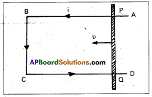
Magnitude of Lorentz force on this charge
(F) = Bqυ ……………….. (1)
Workdone in moving the charge from P to Q is given by ‘
W = Force × displacement
W = Bqυ × l ………………. (2) (∵ Direction of force on the charge as per Flemings left hand rule)
Electromagnetic force (ε) = \(\frac{W}{Q}\)
ε = \(\frac{\mathrm{Bqυl}}{\mathrm{q}}\) ⇒ ε = Blυ ……………. (3)
![]()
Question 2.
Describe the ways in which Eddy currents are used to advantage. [A.P. Mar. 17, 16; A.P. & T.S. Mar. 15]
Answer:
Eddy currents are used to advantage in
i) Magnetic braking in trains : A strong magnetic field is applied across the metallic drum rotating with the axle of the electric train. Thus large eddy currents are produced in the metallic drum. These currents oppose the motion of the drum and hence the axle of the train which ultimately makes the train come to rest.
ii) Induction Motor: Eddy currents are used to rotate the short circuited motor of an induction motor. Ceiling fans are also induction motors which run on single phase alternating current.
iii) Electromagnetic damping : Certain galvanometers have a fixed core made of non magnetic metallic material. When the coil oscillates, the eddy currents generated in the core oppose the motion and bring the coil to rest quickly.
iv) Induction furnace : Induction furnace can be used to produce high temperatures and can be utilised to prepare alloys, by melting the constituent metals. A high frequency alternating current is passed through a coil. The eddy currents generated in the metals produce high temperatures sufficient to melt it.
v) Analogue energy meters : Concept of eddy currents is used in energy meters to record the consumption of electricity. Aluminium disc used in these meters get induced due to varying magnetic field. It rotates due to eddy currents produced in it.
Question 3.
Obtain an expression for the mutual inductance of two long co-axial solenoids.
Answer:
Consider two solenoids as shown in figure. The length of primary coil be l and area of cross section A. Let N1 and N2 are the total number of turns in the primary and secondary solenoids. Let n1 and n2 be the number of turns per unit length
(n1 = \(\frac{\mathrm{N}_1}{l}\) and n2 = \(\frac{\mathrm{N}_2}{l}\)). Current in the primary coil is i.
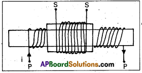
∴ Magnetic field inside the primary (B) = μ0n1 I = μ0 \(\frac{\mathrm{N}_1}{l}\) I ……….. (1)
Magnetic flux through each turn of primary
ΦB = \(\overrightarrow{\mathrm{B}} \cdot \overrightarrow{\mathrm{A}}\) = μ0 \(\frac{\mathrm{N}_1}{l}\) I × A ……………. (2)
The same magnetic flux is linked with the secondary coil.
∴ Total magnetic flux linked with secondary = μ0\(\frac{\mathrm{N}_1 \mathrm{i}}{l}\) × A × N2 ……………. (3)
If M be mutual inductance of the two coils, the total flux linked with the secondary is Mi.
∴ Mi = \(\frac{\mu_0 \mathrm{~N}_1 \mathrm{~N}_2 \mathrm{iA}}{l}\) ……………… (4)
M = \(\frac{\mu_0 \mathrm{~N}_1 \mathrm{~N}_2 \mathrm{~A}}{l}\) …………….. (5) (∵ A = πr2)
(or) M = \(\frac{\mu_0 \mathrm{~N}_1 \mathrm{~N}_2\left(\pi \mathrm{r}^2\right)}{l}\) ………….. (6) (∵μr = \(\frac{\mu}{\mu_0}\))
Problems
Question 1.
A wheel with 10 metallic spokes each 0.5 m long is rotated with a speed of 120 rev/min in a plane normal to the horizontal component of earth’s magnetic field HE at a place. If HE = 0.4 G at the place, what is the induced emf between the axle and the rim of the wheel ? (Note that 1 G = 10-4 T.)
Solution:
Induced emf = (1/2) ω B R2
= (1/2) × 4π × 0.4 × 10-4 × (0.5)2
= 6.28 × 10⁻⁵ V
![]()
Question 2.
Number of turns in a coil are 100. When a current of 5A is flowing through the coil, the magnetic flux is 10-6Wb. Find the self induction. [Board Model Paper]
Solution:
Self inductance, L = \(\frac{n \phi}{\mathrm{i}}\)
number of turns, n = 100; magnetic flux, Φ = 10-6Wb; Current, i = 5A
L = \(\frac{100 \times 10^{-6}}{5}\) = 20 × 10-6 = 20 µH
∴ Self inductance, L = 20 µH
Question 3.
Current in a circuit falls from 5.0 A to 0.0 A in 0.1 s. If an average emf of 200 V is induced, give an estimate of the self-inductance of the circuit. [Mar. 16 (T.S.) Mar. 14]
Solution:
Change in current, dI = 5 – 0 = 5A,
Time taken in current change dt = 0.1 s
Induced average emf eav = 200 V
Induced emf in the circuit e = L . \(\frac{\mathrm{dI}}{\mathrm{dt}}\) ⇒ 200 = L\(\left(\frac{5}{0.1}\right)\) or L = \(\frac{200}{50}\) = 4 H.
Question 4.
A pair of adjacent coils has a mutual inductance of 1.5 H. If the current in one coil changes from 0 to 20 A in 0.5 s, what is the change of flux linkage with the other coil ? [T.S. Mar. 17]
Solution:
Given, mutual inductance of coil M = 1.5 H
Current change in coil dI = 20 – 0 = 20 A
Time taken in change dt = 0.5s, Induced emf in the coil e M = \(M \frac{d I}{d t}=\frac{d \phi}{d t}\)
dΦ = M.dI = 1.5 × 20, dΦ = 30 Wb,
Thus the change of flux linkage is 30 Wb.
![]()
Question 5.
A jet plane is travelling towards west at a speed of 1800 km/K What is the voltage difference developed between the ends of the wing having a span of 25 m, if the Earth’s magnetic field at the location has a magnitude of 5 × 10⁻⁴ T and the dip angle is 30°.
Solution:
Speed of jet plane V = 1800 km/h = 1800 × \(\frac{5}{18}\) = 500 m/s
l = Distance between the ends of wings = 25 m
The magnitude of magnetic field B = 5 × 10⁻⁴ T
Angle of dip γ = 30°.
Use the formula of motional emf
e = BvVl, e = B sin γ Vl (Bv = B sin γ),
e = 5 × 10⁻⁴ × sin 30° × 500 × 25, e = 3.1V
Thus, the voltage difference developed between the ends is 3.1 V.
Textual Examples
Question 1.
(a) What would you do to obtain a large deflection of the galvanometer ?
(b) How would you demonstrate the presence of an induced current in the absence of a gal-vanometer ?
Solution:
a) To obtain a large deflection, one or more of the following steps can be taken :
- Use a rod made of soft iron inside the coil C2.
- Connect the coil to a powerful battery, and
- Move the arrangement rapidly towards the test coil C1.
b) Replace the galvanometer by a small bulb, the kind one finds in a small torch light. The relative motion between the two coils will cause the bulb to glow and thus demonstrate the presence of an induced current.
Question 2.
A square loop of side 10 cm and resistance 0.5 Ω is placed vertically in the east-west plane. A uniform magnetic field of 0.10 T is set up across the plane in the north-east direction. The magnetic field is decreased to zero in 0.70 s at a steady rate. Determine the magnitudes of induced emf and current during this time interval.
Solution:
The angle θ made by the area vector of the loop with the magnetic field is 45°.
From eq. ΦB = B.A. = BA cosθ the initial magnetic flux is Φ = BA cosθ
= \(\frac{0.1 \times 10^{-2}}{\sqrt{2}}\) Wb
Final flux, Φmin = 0
The change in flux is brought about in 0.70 s. From Eq. ε = \(\frac{\mathrm{d} \phi_{\mathrm{B}}}{\mathrm{dt}}\), the magnitude of the induced emf is given by
ε = \(\frac{\left|\Delta \phi_{\mathrm{B}}\right|}{\Delta \mathrm{t}}=\frac{|(\phi-0)|}{\Delta \mathrm{t}}=\frac{10^{-3}}{\sqrt{2} \times 0.7}\) = 1.0 mV
And the magnitude of the current is
I = \(\frac{\varepsilon}{\mathrm{R}}=\frac{10^{-3} \cdot \mathrm{V}}{0.5 \Omega}\) = 2 mA.
Note that the earth’s magnetic field also produces a flux through the loop.
![]()
Question 3.
A circular coil of radius 10 cm, 1500 turns and resistance 2 Ω is placed with its plane perpendicular to the horizontal component of the earth’s magnetic field. It is rotated about its vertical diameter through 180° in 0.25 s. Estimate the magnitudes of the emf and current induced in the coil. .Horizontal component of the earth’s magnetic field at the place is 3.0 × 10⁻⁵ T.
Solution:
Initial flux through the coil,
ΦB(initial) = BA C0S θ
= 3.0 × 10⁻⁵ × (π × 10-2) × cos 0°
= 3π × 10-7 Wb.
Final flux after the rotation,
ΦB(final) = 3.0 × 10⁻⁵ × (π × 10-2) × cos 180°
= -3π × 10-7 Wb.
Therefore, estimated value of the induced emf is,
ε = N\(\frac{\Delta \phi}{\Delta t}\) = 500 × (6π × 10-7)/0.25
= 3.8 × 10⁻³ V
I = ε/R = 1.9. × 10-3 A.
Note that the magnitudes of ε and I are the estimated values.
Question 4.
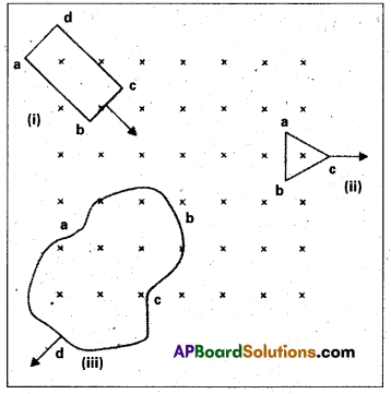
The following figure shows planar loops of different shapes moving out of or into a region of a magnetic field which is directed normal to the plane of the loop away from the reader. Determine the direction of induced current in each loop using Lenz’s law.
Solution:
- The magnetic flux through the rectangular loop abed increases, due to the motion of the loop into the region of magnetic field. The induced current must flow along the path bcdab so that it opposes the increasing flux.
- Due to the outward motion, magnetic flux through the triangular loop abc decreases due to which the induced current flows along bacd, so as to oppose the change in flux.
- As the magnetic flux decreases due to motion of the irregular shaped loop abed out of the region of magnetic field, the induced current flows along edabe, so as to oppose change in flux.
![]()
Question 5.
a) A closed loop is held stationary in the magnetic field between the north and south poles of two permanent magnets held fixed. Can we hope to generate current in the loop by using very strong magnets ?
b) A closed loop moves normal to the constant electric field between the plates of a large capacitor. Is a current induced in the loop (i) when it is wholly inside the region between the capacitor plates (ii) When it is partially outside the plates of the capacitor ? The electric field is normal to the plane of the loop.
c) A rectangular loop and a circular loop are moving out of a uniform magnetic field region as in the figure, to a field-free region with a constant velocity v. In which loop do you expect the induced emf to be constant during the passage out of the field region ? The field is normal to the loops.

d) Predict the polarity of the capacitor in the situation described by the following figure.

Solution:
a) No. However strong the magnet may be, current can be induced only by changing the magnetic flux through the loop.
b) No current is induced in either case. Current can not be induced by changing the electric flux.
c) The induced emf is expected to be constant only in the case of the rectangular loop. In the case of circular loop, the rate of change of area of the loop during its passage out of the field region is not constant, hence induced emf will vary accordingly.
d) The polarity of plate ‘A’ will be positive with respect to plate ‘B’ in the capacitor.
Question 6.
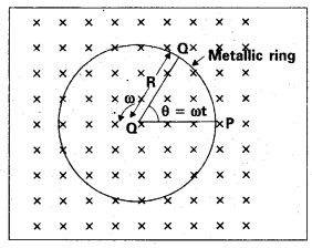
A metallic rod of 1 m length is rotated with a frequency of 50 rev/s, with one end hinged at the centre and the other end at the circumference of a circular metallic ring of radius 1 m, about an axis passing through the centre and perpendicular to the plane of the ring as in figure. A constant and uniform magnetic field of 1 T parallel to the axis is present everywhere. What is the emf between the centre and the metallic ring ?
Solution:
Method I : As the rod is rotated, free electrons in the rod move towards the outer end due to Lorentz force and get distributed over the ring. Thus, the resulting separation of charges produces an emf across the ends of the rod. At a certain value of emf, there is no more flow of electrons and a steady state is reached.
Using equation (ε = – Bl \(\frac{\mathrm{dx}}{\mathrm{dt}}\) = BlV), the magnitude of the emf generated across a length dr of the rod as it moves at right angles to the magnetic field is given by
dε = Bυ dr. Hence,
ε = \(\int \mathrm{d} \varepsilon=\int_0^{\mathrm{R}} \mathrm{B} v \mathrm{dr}=\int_0^{\mathrm{R}} \mathrm{B} \omega \mathrm{rdr}=\frac{\mathrm{B} \omega \mathrm{R}^2}{2}\)
Note that we have used υ = ωr. This gives
ε = \(\frac{1}{2}\) × 1.0 × 2π × 50 × (12) = 157 V.
Method II: To calculate the emf, we can imagine a closed loop OPQ in which point O and P are connected with a resistor R and OQ is the rotating rod. The potential difference across the resistor is then equal to the induced emf and equals B × (rate of change of area of loop). If θ is the angle between the rod and the radius of the circle at P at time t, the area of the sector OPQ is given by
πR2 × \(\frac{\theta}{2 \pi}=\frac{1}{2}\), R2θ
where R is the radius of the circle. Hence, the induced emf is
e = B × \(\frac{\mathrm{d}}{\mathrm{dt}}\left[\frac{1}{2} \mathrm{R}^2 \theta\right]=\frac{1}{2} \mathrm{BR}^2 \frac{\mathrm{d} \theta}{\mathrm{dt}}=\frac{\mathrm{B} \omega \mathrm{R}^2}{2}\)
[Note: \(\frac{\mathrm{d} \theta}{\mathrm{dt}}\) = ω = 2πv]
This expression is identical to the – expression obtained by Method I and we get the same value of ε.
![]()
Question 7.
A wheel with 10 metallic spokes each 0.5 m long is rotated with a speed of 120 rev/min in a plane normal to the horizontal component of earth’s magnetic field HE at a place. If HE = 0.4 G at the place, what is the induced emf between the axle and the rim of the wheel ? Note that 1 G = 10-4 T.
Solution:
Induced emf = (1/2) ω B R2
= (1/2) × 4π × 0.4 × 10-4 × (0.5)2
= 6.28 × 10⁻⁵ V
Question 8.
Refer to fig. The arm PQ of the rectangular conductor is moved from x = 0, outwards. The uniform magnetic field is perpendicular to the plane and extends from x = 0 to x = b and is zero for x > b. Only the arm PQ possesses substantial resistance r. Consider the situation when the arm PQ is pulled outwards from x = 0 to x = 2b, and is then moved back to x = 0 with constant speed o. Obtain expressions for the flux, the induced emf, the force necessary to pull the arm and the power dissipated as Joule heat. Sketch the variation of these quantities with distance.
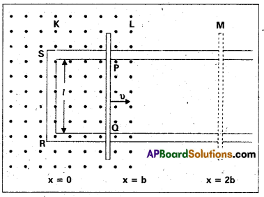
Solution:
Let us first consider the forward motion from x = 0 to x = 2b. The flux ΦB linked with the circuit SPQR is
ΦB = Blx 0 ≤ x < b
= Blυ b ≤ x < 2b
The induced emf is,
ε = – \(\frac{\mathrm{d} \phi_{\mathrm{B}}}{\mathrm{dt}}\)
= -Blυ 0 ≤ x < b
= 0 b ≤ x < 2b.
When the induced emf is non-zero, the current I is (in magnitude)
I = \(\frac{\mathrm{B} l v}{\mathrm{r}}\)
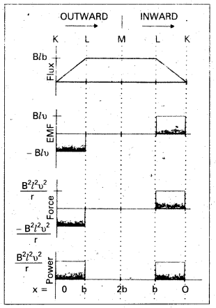
The force required to keep the arm PQ in constant motion is I lB. Its direction is to the left. In magnitude
F = \(\frac{\mathrm{B}^2 l^2 v}{\mathrm{r}}\) 0 ≤ x < b
= 0 b ≤ x < 2b
The Joule heating loss is
Pj = I2r
= \(\frac{\mathrm{B}^2 l^2 v^2}{\mathrm{r}}\) 0 ≤ x < b
= 0 b ≤ x < 2b
One obtains similar expressions for the inward motion from x = 2b to x = 0.
![]()
Question 9.
Two concentric circular coils, one of small radius r1 and the other of large radius r2, such that r1 << r2, are placed co-axially with centres coinciding. Obtain the mutual inductance of the arrangement.
Solution:
Let a current I2 flow through the outer circular coil. The field at the centre of the coil is B2 = μ0I2/2r2. Since the other co-axially placed coil has a very small radius. B2 may be considered constant over its cross-sectional area. Hence,
Φ2 = \(\pi \mathrm{r}_1^2 \mathrm{~B}_2\)
= \(\frac{\mu_0 \pi \mathrm{r}_1^2}{2 \mathrm{r}_2} \mathrm{I}_2\)
= M12I2
Thus,
M12 = \(\frac{\mu_0 \pi r_1^2}{2 r_2}\)
From Equation M12 = M21 = M
M12 = M21 = \(\frac{\mu_0 \pi r_1^2}{2 r_2}\)
Note that we calculated M12 from an approximate value of Φ1 assuming the magnetic field B2 to be uniform over the area \(\pi r_1^2\). However, we can accept this value because r1 << r2.
Question 10.
(a) Obtain the expression for the magnetic energy stored in a solenoid in terms of magnetic field B, area A and length l of the solenoid.
(b) How does this magnetic energy compare with the electrostatic energy stored in a capacitor ?
Solution:
a) From Equation ε = – L \(\frac{\mathrm{dI}}{\mathrm{dT}}\),
the magnetic energy is
UB = \(\frac{1}{2}\) LI2
= \(\frac{1}{2} \mathrm{~L}\left(\frac{\mathrm{B}}{\mu_0 \mathrm{n}}\right)^2\)
(since B = μ0nI, for a solenoid)
= \(\frac{1}{2}\) (μ0n2Al) \(\left(\frac{\mathrm{B}}{\mu_0 \mathrm{n}}\right)^2\)
[from Equation L = μ0n2Al]
= \(\frac{1}{2 \mu_0}\) B2Al
b) The magnetic energy per unit volume is,
uB = \(\frac{\mathrm{U}_{\mathrm{B}}}{\mathrm{V}}\)
[where Vis volume that contains flux]
= \(\frac{\mathrm{U}_{\mathrm{B}}}{\mathrm{Al}}=\frac{\mathrm{B}}{2 \mu_0}\) ……………….. (1)
We have already obtained the relation for the electrostatic energy stored per unit volume in a parallel plate capacitor.
uE = \(\frac{1}{2}\) ε0E2 ………………. (2)
In both the cases energy is proportional to the square of the field strength.
![]()
Question 11.
Kamla peddles a stationary bicycle, the pedals of the bicycle are attached to a 100 turn coil of area 0.10 m2. The coil rotates at half a revolution per second and it is placed in a uniform magnetic field of 0.01 T perpendicular to the axis of rotation of the coil. What is the maximum voltage generated in the coil ?
Solution:
Here f = 0.5 Hz; N = 100, A = 0.1 m2 and B = 0.01 T.
Employing Equation ε = NBA ω sin ωt
ε0 = NBA (2πv)
= 100 × 0.01 × 0.1 × 2 × 3.14 × 0.5
= 0.314 V
The maximum voltage is 0.314 V